
Continuous Casting and Rolling Installation For Producing a Steel Strip

a technology of continuous casting and rolling installation, which is applied in the direction of manufacturing tools, work heating devices,foundry moulding apparatus, etc., can solve the problem of limited amount of re-forming work, and achieve the effect of simple manner

Inactive Publication Date: 2008-06-12
SIEMENS AG
View PDF9 Cites 6 Cited by
  • Summary
  • Abstract
  • Description
  • Claims
  • Application Information

AI Technical Summary

Benefits of technology

"The present invention is a continuous casting and rolling installation for producing high-grade steel strips. It includes a reduction device with multiple roll pairs and a technological control system that takes into account the thermal behavior of the steel or steel strip. The reduction device reduces the thickness of the steel strip before it enters the rolling mill, which simplifies the forming work required to produce the finished product. The control system guides the installation parts based on a material model that takes into account the chemical composition, mechanical treatment, and thermal history of the steel or steel strip. The installation parts include a mold, a reduction device, a cooling section, a rolling mill, and a descaler. The invention allows for the efficient production of high-quality steel strips with minimal re-forming work."

Problems solved by technology

Since this reduction takes place at high temperatures, possibly even before complete solidification of the steel strip, only a limited amount of re-forming work is likewise required for this reduction.

Method used


Image

  • Continuous Casting and Rolling Installation For Producing a Steel Strip
  • Continuous Casting and Rolling Installation For Producing a Steel Strip
  • Continuous Casting and Rolling Installation For Producing a Steel Strip

Examples


Embodiment Construction

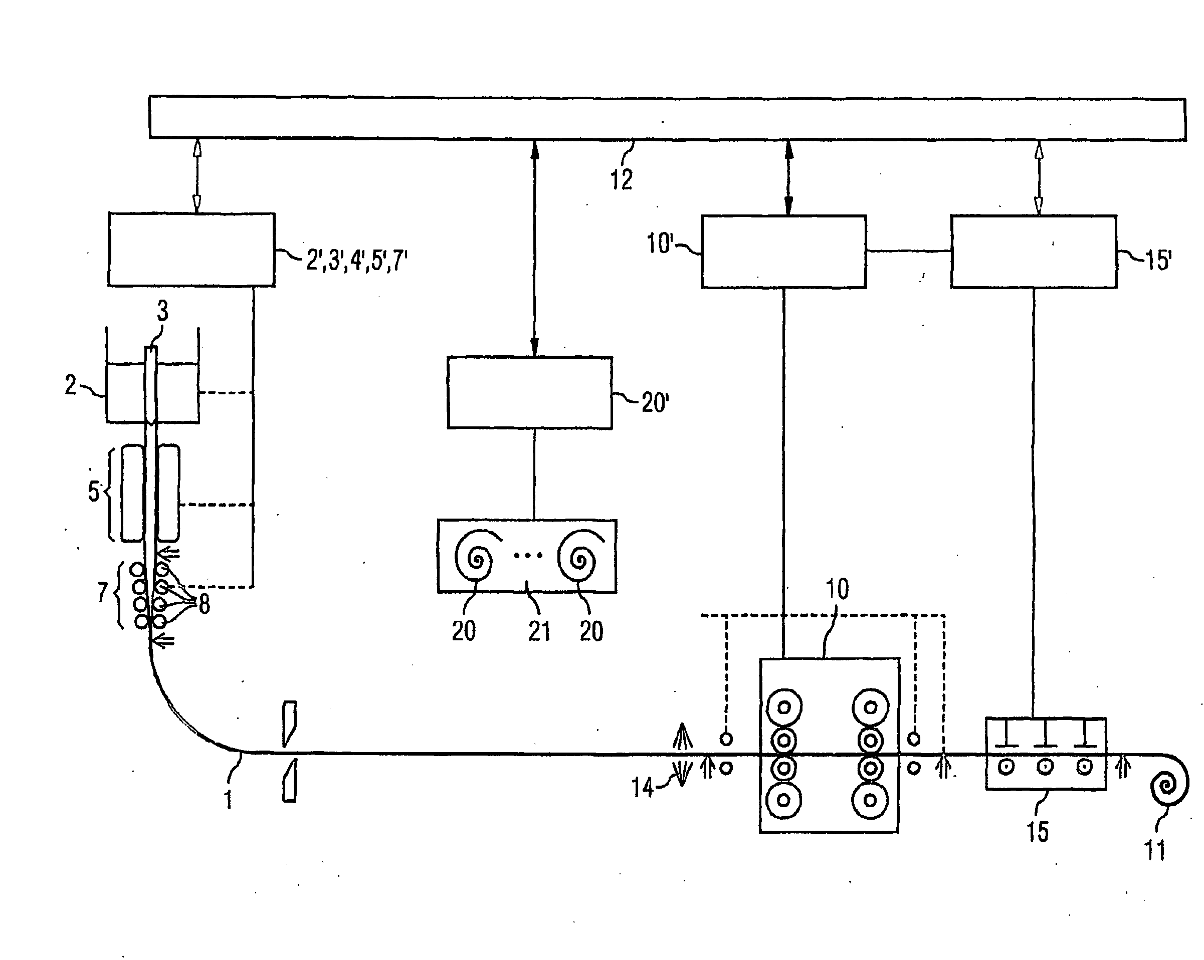
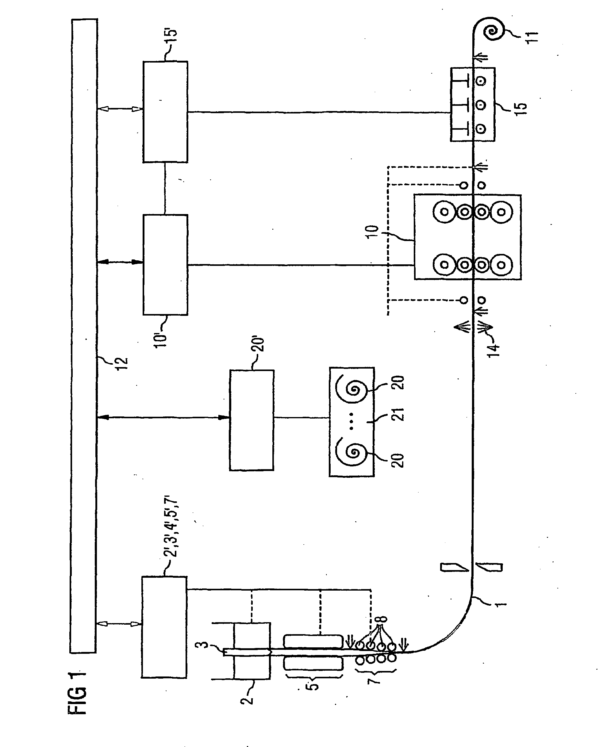
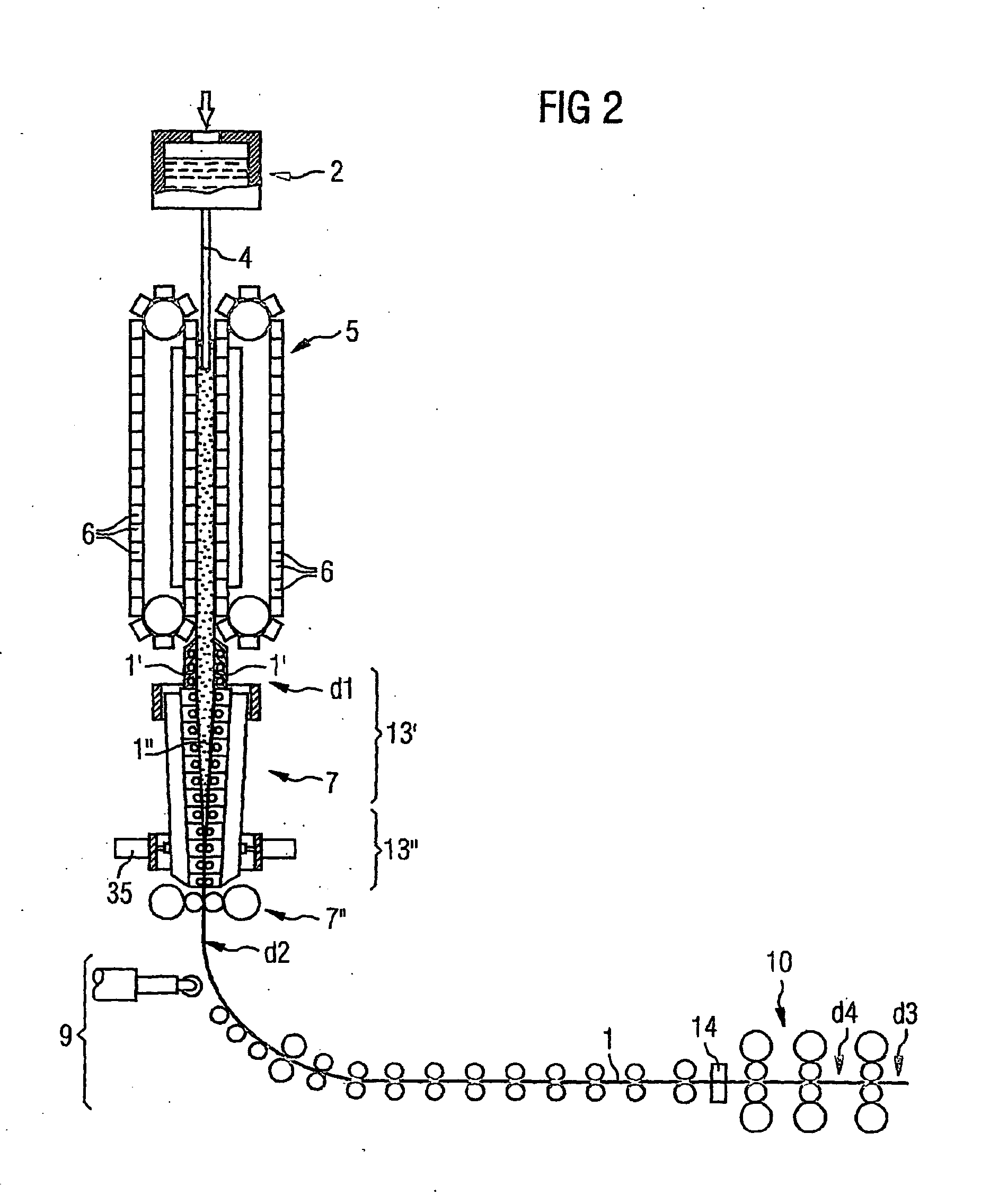
[0035]According to FIG. 1, a continuous casting and rolling installation for producing a steel strip 1 comprises firstly a liquid steel storage device 2. This device 2 is usually designed as a so-called tundish. Liquid steel passes from the tundish 2 via a liquid steel charging device 3, indicated only schematically, (e.g. a liftable plug) and an immersion tube 4 into a casting device 5. The casting level is precisely controlled in a known manner to an accuracy of a few mm, e.g. ±3 mm.

[0036]The casting device 5 in the present case is fashioned as a vertically operating casting device 5. It comprises a plurality of plates 6 which are connected to one another to form a continuous chain and revolve with the cast steel strip 1. The plates 6 thus together form a revolving mold 6. The steel strip 1 flows out of the mold 6 with a casting thickness d1 and a strip width b.

[0037]Arranged downstream of the casting device 5 is a reduction device 7. The reduction device 7 comprises a plurality o...


PUM

PropertyMeasurementUnit
thicknessaaaaaaaaaa
thicknessaaaaaaaaaa
thicknessaaaaaaaaaa

Abstract

In order to produce a steel strip (1), a continuous casting and rolling installation comprises a liquid steel storage device (2), a liquid steel charging device (3), a vertically operating casting device (5) with a revolving mold (6), a reduction device (7) with a plurality of roll pairs (8), a diverting device (9) for diverting the cast steel strip (1) into a horizontal position, a horizontally operating rolling mill (10) and a winding device (11), which are controlled via individual technological control loops (2′ to 11′). In order to adjust the technological control loops (2′ to 11′) in an integrated manner, it also comprises a control system (12) which connects the installation parts (2 to 11) or components with regard to control, operates on the basis of mathematical models (17), and coordinates the individual installation parts (2 to 11) with regard to the interaction thereof, while taking into consideration the effects of the control steps of an installation part (2 to 11) upon installation parts (2 to 11) following in the direction of mass flow. The control system (12) contains a material model (17), by means of which a thermal behavior of the steel or steel strip (1) from the steel storage device (2) to the winding device (11) can be modeled using path tracking. The technological control loops (2′ to 11′) are controlled at the correct times according to the modeled thermal behavior of the steel or steel strip (1).

Description

CROSS REFERENCE TO RELATED APPLICATIONS[0001]This application is the US National Stage of International Application No. PCT / EP2004 / 001694, filed Feb. 20, 2004 and claims the benefit thereof. The International Application claims the benefits of German application No. 10310357.0, filed Mar. 10, 2003, both applications are incorporated by reference herein in their entirety.FIELD OF INVENTION[0002]The present invention relates to a continuous casting and rolling installation for producing a steel strip, comprising a liquid steel storage device, a liquid steel charging device, a vertically operating casting device with a revolving mold, a diverting device for diverting the cast steel strip into a horizontal position, a horizontally operating rolling mill and a winding device, all components being guided and / or controlled via individual technological control loops, the continuous casting and rolling installation comprising, in order to adjust the technological control loops in an integrat...

Claims


Application Information

Patent Timeline
Patent Type & Authority Applications(United States)
IPC IPC(8): B22D45/00B22D11/16B21B1/24B21B1/46B21B37/00B21B37/74B21B45/00B22D11/06B22D11/12
CPCB21B1/24B21B1/463B21B1/466B21B37/00B21B37/74B22D11/16B21B2015/0057B21B2201/14B21B2201/18B22D11/06B22D11/1206B21B45/004B22D11/0608
Inventor DOLL, RUDIGERPRONOLD, KLAUSSIEBER, ALBRECHT
Owner SIEMENS AG
Learn More