Measurement Arrangement for Determining the Characteristic line Parameters by Measuring Scattering Parameters

a measurement arrangement and scattering technology, applied in the direction of instruments, measurement devices, resistance/reactance/impedence, etc., can solve the problems of high frequency measurement band limitation to less than 4 ghz and alter the measuremen

Inactive Publication Date: 2008-06-12
IBM CORP
View PDF2 Cites 2 Cited by
  • Summary
  • Abstract
  • Description
  • Claims
  • Application Information

AI Technical Summary

Benefits of technology

[0027]Preferably, neighboring layer lines arranged directly adjacent to each other have a different impedance on their first ends and their second ends, so that the first ends and second ends of all neighboring layer lines are alternatingly terminated by a low impedance and a high impedance, respectively. This alternating arrangement of the neighboring layer lines in connection with the alternating arrangement of neighboring signal lines lead to a significant gain of measurement bandwidth. Experiments have shown that due to the inventive arrangement of on chip wiring the bandwidth is increased up to 20 GHz.

Problems solved by technology

A problem occurs when parallel lines on the test site have to be connected to some point in absence of drivers, receivers and transistors.
One option is to leave both sides of the signal lines open, but floating lines do not correspond to the product and will therefore alter the measurement results.
This option imitates the product but the problem that occurs here is that high frequency measurements are band limited to less than 4 GHz because in the higher frequency range both measurements ports present a different electrical behavior on both ports.

Method used


Image

  • Measurement Arrangement for Determining the Characteristic line Parameters by Measuring Scattering Parameters
  • Measurement Arrangement for Determining the Characteristic line Parameters by Measuring Scattering Parameters
  • Measurement Arrangement for Determining the Characteristic line Parameters by Measuring Scattering Parameters

Examples


Embodiment Construction

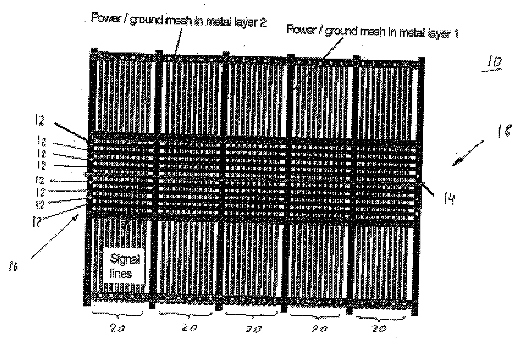
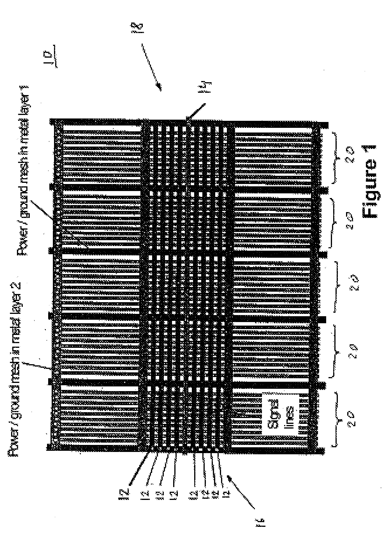
[0037]FIG. 1 shows a schematic view of a multi-layer chip 10 having an unsymmetrical connection pattern of the signal lines (State of the art).

[0038]In order to image the real signal coupling behavior on the chip 10 additional signal lines 12, the so-called neighboring signal lines, were added adjacent to a signal line under test 14, the so-called measuring line, in the same layer.

[0039]The neighboring signal lines 12 were connected by vias to ground on one side 16, here port 1, to imitate a driver and left open on the opposite side 18, here port 2, to imitate a receiver.

[0040]In order to image the shielding effect of metal layers between top metal layers and the semi conducting substrate additional signal lines 20, the so-called neighboring layer lines, were added in the bottom metal layers. All neighboring signal lines 20 were also connected to ground on one side and left open on the opposite side.

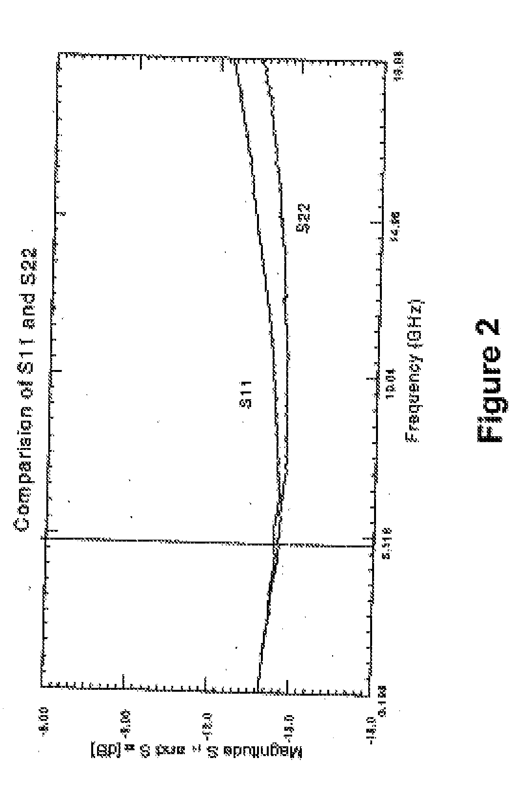
[0041]As a result the measured reflection parameters S11 and S22 as depicted in FIGS...


PUM


Abstract

The present invention relates to a measurement arrangement for determining the characteristic line parameters by measuring the S-parameters as a function of the frequency of an electrical signal line that achieves an increased measurement bandwidth, namely a measurement bandwidth >4 GHz. To achieve this the electrical signal line under test has several neighboring signal lines which are connected to ground on one side and left open on the opposite side in an alternating manner.

Description

[0001]The present invention relates to a measurement arrangement for determining the characteristic line parameters by measuring scattering parameters (S-parameters) as a function of the frequency of an electrical signal line according to the features of claim 1.BACKGROUND OF THE INVENTION[0002]Model to hardware correlation measurements on all packaging levels are essential in today's development process of high performance computers. Different measurement techniques in time and frequency domain require different measurement set-ups and test site designs. One demand for the test site is to be equivalent to the product. Therefore, transmission lines on a chip need to be measured in the product line power and ground wiring distributed in all metal layers on chip. In addition it is not only of interest to measure a single transmission line but also with a product like wiring channel utilization. This is essential to image the real signal coupling behavior on the chip and the shielding ...

Claims


Application Information

Patent Timeline
Patent Type & Authority Applications(United States)
IPC IPC(8): G01R27/00
CPCG01R31/021G01R27/04G01R31/58
Inventor LUDWIG, THOMASSCHETTLER, HELMUTWINKEL, THOMAS-MICHAEL
Owner IBM CORP
Why Eureka
Try Eureka