Phase modulator frequency response measurement method and device

A phase modulator and measurement method technology, applied in the direction of testing optical performance, etc., can solve the problems that the frequency response of the phase modulator cannot be measured, the complexity is difficult to implement, and the matching requirements are relatively high, so as to achieve high test efficiency, good stability, and measurement high resolution effects

Inactive Publication Date: 2017-09-29
NANJING UNIV OF AERONAUTICS & ASTRONAUTICS
View PDF11 Cites 1 Cited by
  • Summary
  • Abstract
  • Description
  • Claims
  • Application Information

AI Technical Summary

Problems solved by technology

Many scientific researchers have done in-depth research on this, for example, the traditional light wave component analysis method, but this method has relatively high requirements for matching and has certain limitations
[0005] At the same time, the traditional light wave component analysis method cannot measure the frequency response of the phase modulator. For this, Bao Xiaobin et al. proposed to measure one of the important parameters of the phase modulator in the article "High frequency measurement and characterization on high-speed electronic phase modulator". ——Half-wave voltage, including optical carrier zero point method, first-order optical sideband and carrier strength ratio method, heterodyne method, etc., so as to obtain the high-frequency characteristics of the phase modulator
However, this method is complex and difficult to implement, so we urgently need to study a new measurement method to improve the accuracy, and at the same time study the universality of the measurement method, and measure the frequency response of various types of electro-optic phase modulators with higher bandwidth

Method used


Image

  • Phase modulator frequency response measurement method and device
  • Phase modulator frequency response measurement method and device
  • Phase modulator frequency response measurement method and device

Examples


Embodiment Construction

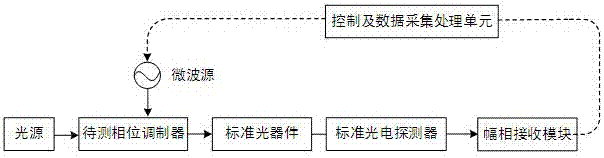
[0023] Aiming at the deficiencies of the prior art, the solution of the present invention is: use the phase modulator to be tested to modulate the microwave signal on the optical carrier to generate an optical phase modulation signal; let the optical phase modulation signal pass through a standard optical device, so that at least part The optical phase modulation signal is converted into an optical intensity modulation signal, and the frequency response of the amplitude and phase of the standard optical device is known; the standard photodetector is used to convert the output optical signal of the standard optical device into an electrical signal, and extract the The amplitude and phase information of the electrical signal, the frequency response of the amplitude and phase of the standard photodetector is known; change the frequency of the microwave signal and repeat the above process, that is, the phase modulator to be tested, the standard optical device and the standard The c...


PUM


Abstract

The invention discloses a phase modulator frequency response measurement method. Microwave signals are modulated on optical carriers by using a phase modulator to be measured so as to generate optical phase modulation signals; the optical phase modulation signals are enabled to pass through a standard optical device so that at least partial optical phase modulation signals are enabled to be converted into optical intensity modulation signals; the output optical signals of the standard optical device are converted into electric signals by using a standard photoelectric detector and the amplitude and phase information of the electric signals is extracted, wherein the frequency response of the amplitude and the phase of the standard optical device and the standard photoelectric detector is known; the frequency of the microwave signals is changed and the process is repeated so that the combined frequency response of the amplitude and the phase of the phase modulator to be measured, the standard optical device and the standard photoelectric detector can be obtained; and finally the amplitude and phase response of the standard optical device and the standard photoelectric detector is removed from the combined frequency response so that the amplitude and phase frequency response of the phase modulator to be measured can be obtained. The invention also discloses a phase modulator frequency response measurement device.

Description

technical field [0001] The invention relates to a frequency response measurement method and device of a phase modulator, and belongs to the technical field intersecting electro-optic device measurement and microwave photonics. Background technique [0002] Optical fiber communication has many advantages such as anti-electromagnetic interference, anti-corrosion, light weight, and large capacity, so it is widely used in many fields such as high-energy physics, anti-nuclear radiation communication systems, submarines, warships, aircraft, missile control communication systems, and the Internet. At present, optical fiber communication is developing in the direction of high speed, high efficiency, large capacity and long distance optical fiber transmission. As the degree of informatization becomes higher and higher, corresponding requirements are put forward for the speed of the optical fiber communication transmission system. [0003] With the continuous progress and development...

Claims


Application Information

Patent Timeline
Patent Type & Authority Applications(China)
IPC IPC(8): G01M11/02
CPCG01M11/02
Inventor 薛敏潘时龙衡雨清王祥传
Owner NANJING UNIV OF AERONAUTICS & ASTRONAUTICS
Why Eureka
Try Eureka