
Drilling system comprising a plurality of borehole telemetry systems

Inactive Publication Date: 2008-06-12
WEATHERFORD TECH HLDG LLC
View PDF10 Cites 40 Cited by
  • Summary
  • Abstract
  • Description
  • Claims
  • Application Information

AI Technical Summary

Benefits of technology

[0008]As mention previously, telemetry data transmission rates or telemetry bandwidths of LWD or MWD systems are relatively small in relation to comparable wireline systems. The invention can be embodied to increase data transmission rates to the surface of the earth. This is accomplished by operationally connecting in parallel two or more telemetry systems to a single sensor thereby obtaining redundant transmission and increasing the transmission bandwidth of the sensor.
[0009]The invention can also be embodied to increase reliability of LWD and MWD data telemetry. Once again, this is accomplished by operationally connecting two or more telemetry systems to a single sensor thereby providing redundant, parallel data transmission from the single sensor. If one transmission channel becomes noisy or fails, transmission to the surface is maintained through the parallel channel.
[0010]Embodied to employ geosteering techniques, the borehole assembly comprises one or more MWD and one or more LWD sensors. As discussed above, the physical configuration of the borehole assembly often segregates MWD and LWD sensors, and electrical connection of these sensors to a common downhole telemetry unit is typically unreliable and not operationally practical. A single telemetry system multiplexed to transmit both MWD and LWD data is, therefore, not desirable. Using capabilities of the present invention, LWD and MWD sensors cooperate with dedicated telemetry systems. Borehole components of the telemetry systems are disposed in close physical proximity to their assigned sensors. This negates telemetry problems introduced by the physical segregation of LWD and MWD sensors. It should also be understood that two or more telemetry systems can be dedicated to each MWD and LWD sensor thereby increasing data transmission rates and data transmission reliability as discussed in the previous paragraphs.

Problems solved by technology

As discussed above, the physical configuration of the borehole assembly often segregates MWD and LWD sensors, and electrical connection of these sensors to a common downhole telemetry unit is typically unreliable and not operationally practical.
A single telemetry system multiplexed to transmit both MWD and LWD data is, therefore, not desirable.

Method used


Image

  • Drilling system comprising a plurality of borehole telemetry systems
  • Drilling system comprising a plurality of borehole telemetry systems
  • Drilling system comprising a plurality of borehole telemetry systems

Examples


Embodiment Construction

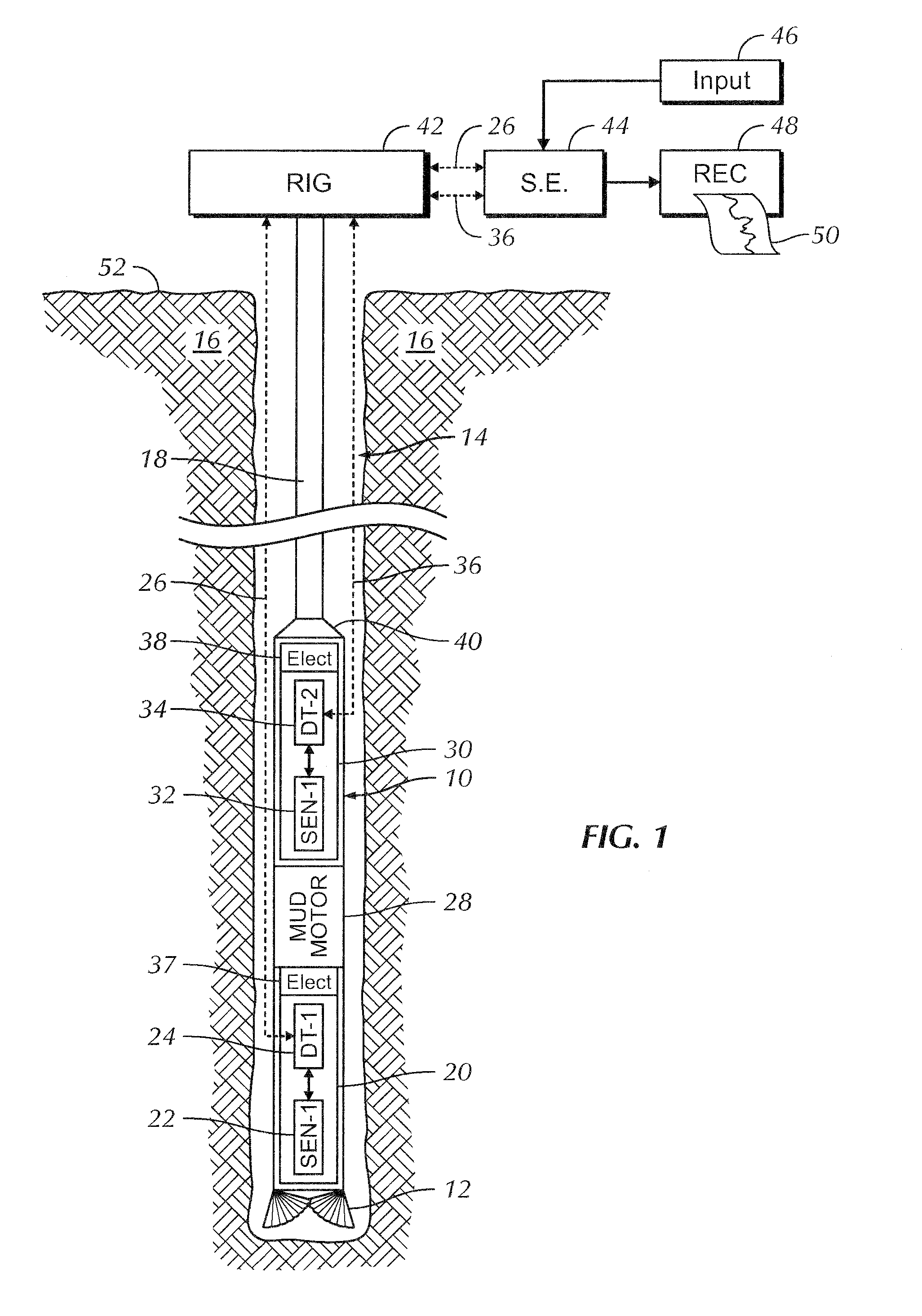
[0018]Basic concepts of a drilling system comprising a plurality of independent telemetry systems will be illustrated using a system comprising a single MWD sensor, a single LWD sensor, and two telemetry systems.

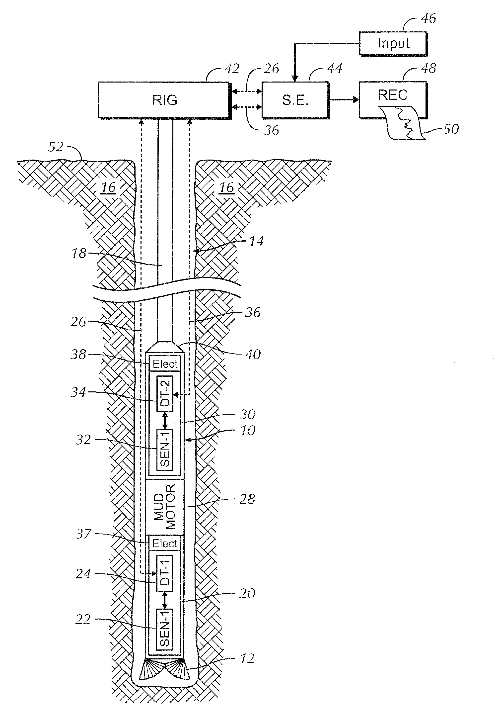
[0019]FIG. 1 illustrates the drilling system in a borehole environment. A drill collar preferably functions as a pressure housing for a borehole assembly 10. The borehole assembly 10 terminates at a lower end with a drill bit 12. The borehole assembly 10 is shown suspended by means of a drill string 18 within a borehole 14 penetrating an earth formation 16. The upper end of the borehole assembly 10 is operationally connected to the lower end of a drill string 18 by a suitable connector 40. The upper end of the drill string is operationally attached to a rotary drilling rig that is well known in the art, and is illustrated conceptually at 42.

[0020]Again referring to FIG. 1, a MWD subsection 20 comprising directional drilling steering apparatus is disposed within the borehole ...


PUM


Abstract

A drilling system utilizing a plurality of independent telemetry systems. The drilling system uses a drill collar as a pressure housing for downhole components of the system. One or more sensors are disposed within the pressure housing. These sensors can be MWD sensors, LWD sensors, or both MWD and LWD sensors. A plurality of independent borehole telemetry systems is used to telemeter sensor response data to the surface of the earth. Each sensor cooperates with a downhole component of at least one of the independent telemetry systems. The plurality of telemetry systems can be of the same type, such as a mud pulse systems. Alternately, the telemetry systems can be of different types including a mud pulse system and an electromagnetic system.

Description

CROSS-REFERENCE TO RELATED APPLICATIONS[0001]This invention is directed toward measurements made within a borehole during the drilling of the borehole. More particularly, the invention is directed toward an measurement-while-drilling or a logging-while-drilling or a combination measurement-while-drilling and logging while drilling system comprising plurality of telemetry systems for communicating between a borehole assembly and the surface of the earth.BACKGROUND OF THE INVENTION[0002]It is often operationally and economically advantageous to obtain measurements of certain parameters of interest during the drilling of a well borehole. Systems for obtaining measurements relating to the drilling operation are commonly referred to as measurement-while-drilling or “MWD” systems. MWD systems typically yield measures of a plurality of borehole conditions, the orientation and path of the borehole assembly, and other drilling related parameters of interest. Systems for obtaining measurement...

Claims


Application Information

Patent Timeline
IPC IPC(8): G01V3/00
CPCE21B47/12E21B47/18E21B7/068
Inventor AIELLO, ROBERT ANTHONYLARRONDE, MICHAEL LOUISMARTIN, JOHNFARLEY, STEVEN R.TOWNS, KIRK
Owner WEATHERFORD TECH HLDG LLC
Learn More