Image Display Apparatus, Image Display Monitor and Television Receiver

Inactive Publication Date: 2008-06-12
SHARP KK
View PDF54 Cites 53 Cited by
  • Summary
  • Abstract
  • Description
  • Claims
  • Application Information

AI Technical Summary

Benefits of technology

[0019]Therefore, the plurality of distributing means each of which has a different luminance distribution ratio for the sub-frames can be used while being switched among them by the switching means, and in the case of trying to suppress the unfocused moving image, it is possible to carry out the luminance distribution for the sub-frames by using the distributing means which has the high effect of suppressing the unfocused

Problems solved by technology

However, when the display apparatus which uses the hold display element carries out the above pseudo impulse driving to improve the performance of the moving image, the problem is that flicker tends to occur (this problem is caused also b

Method used


Image

  • Image Display Apparatus, Image Display Monitor and Television Receiver
  • Image Display Apparatus, Image Display Monitor and Television Receiver
  • Image Display Apparatus, Image Display Monitor and Television Receiver

Examples


embodiment 1

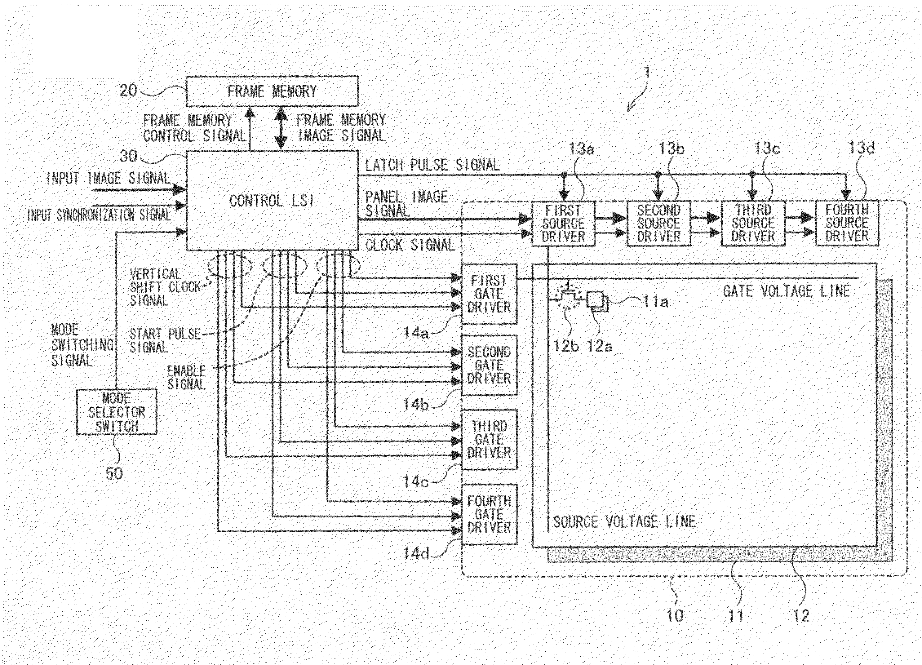
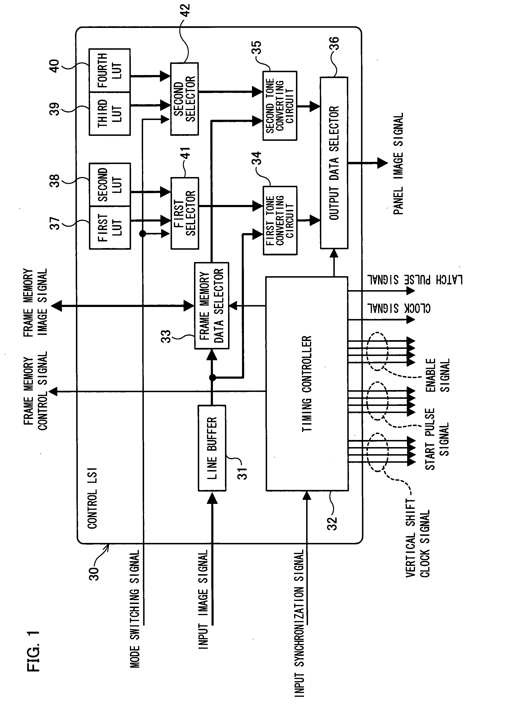
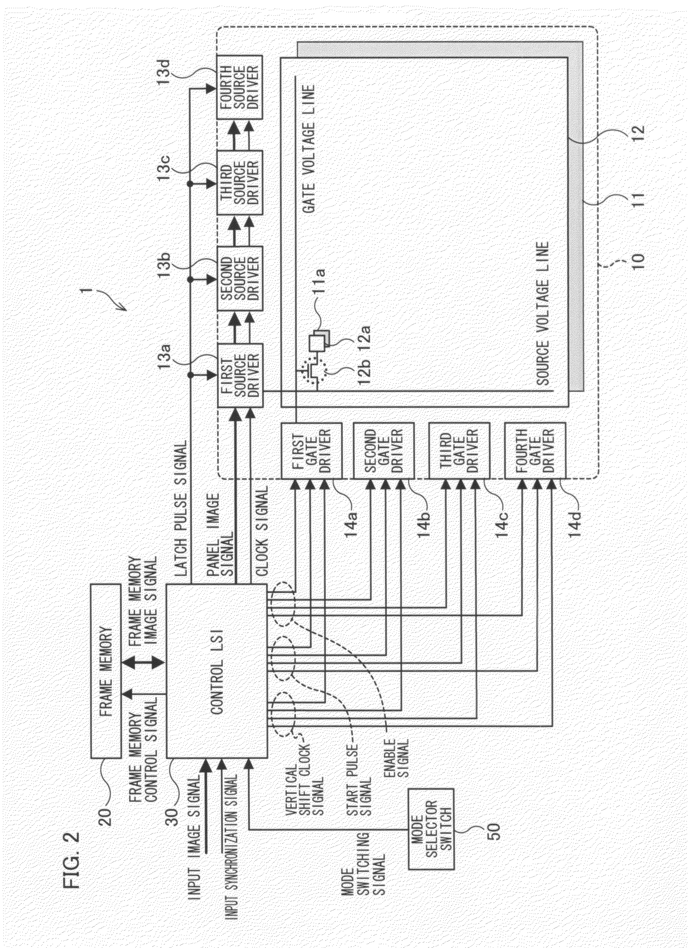
[0062]The following will explain one embodiment of the present invention on the basis of FIGS. 1 to 5. First explained below is a schematic arrangement of an image display apparatus of the present embodiment 1 in reference to FIG. 2. In FIG. 2, an image display apparatus 1 includes a display panel 10, a frame memory 20, a control LSI 30 and a mode selector switch 50.

[0063]The display panel 10 constitutes image displaying means, and includes a display element array 11, a TFT substrate 12, source drivers 13a to 13d, and gate drivers 14a to 14d. In the display element array 11, a plurality of display elements 11a (pixel portions), such as liquid crystal materials or organic EL members, are arranged in a matrix manner.

[0064]In a display area of the TFT substrate 12, (i) pixel electrodes 12a which drives the display elements 11a, and (ii) TFTs 12b that are switching elements which turn on or off electric charge supply (display voltage) to the pixel electrodes 12a are respectively arrange...

embodiment 2

[0110]The image display apparatus of the present embodiment 2 is shown in FIG. 6. The image display apparatus 2 shown in FIG. 6 is different from the image display apparatus 1 shown in FIG. 2 in that the mode selector switch 50 is not included, and a control LSI 60 is included instead of the control LSI 30. The other members in the image display apparatus 2 are the same as those in the image display apparatus 1, so that the same reference numerals are used for the members having the same functions as the members, shown in FIG. 2, in the image display apparatus 1, and detailed explanations thereof are omitted here.

[0111]In the image display apparatus 2, the control LSI 60 determines based on the input image signal whether the display image is the moving image or the still image, and the control LSI 60 selects an appropriate display mode in accordance with the result of the determination. That is, since the time-division driving of the image display apparatus of the present invention ...

embodiment 3

[0117]An image display apparatus of the present embodiment 3 is substantially the same as the image display apparatus 2 shown in FIG. 6 except that a control LSI 70 shown in FIG. 8 is included instead of the control LSI 60. The control LSI 70 is obtained by replacing the moving / still image determining circuit 61 of the control LSI 60 shown in FIG. 7 with a luminance measuring circuit 71.

[0118]In the image display apparatus of the present embodiment 3, the control LSI 70 measures (calculates) average luminance of the input image signal, and selects an appropriate display mode in accordance with the result of the measurement (calculation). That is, in the time-division driving in the image display apparatus of the present invention, generally, the flicker tends to occur when the luminance of the display image is high, and the flicker hardly occurs when the luminance of the display image is low. Therefore, it is preferable that (i) when the luminance of the display image is low, the di...


PUM


Abstract

A control LSI (30) time-divides one frame period of an input image signal into a plurality of sub-frame periods and outputs the signal to a display panel, so as to carry out image display by pseudo impulse driving. At this time, in a first display mode, a first tone converting circuit (34) refers to a first table (37), and a second tone converting circuit (35) refers to a third table (39), to generate an image signal of each sub-frame from the input image signal. In a second display mode, the first tone converting circuit (34) refers to a second table (38), and the second tone converting circuit (35) refers to a fourth table (40), to generate the image signal of the sub-frame from the input image signal. Each of a first selector (41) and a second selector (42) switches the tables to be referred in accordance with a mode switching signal. Thus, it is possible to realize an image display apparatus which can effectively obtain an effect of suppressing an unfocused moving image by the pseudo impulse driving and reduce the problem of the flicker caused by the pseudo impulse driving.

Description

TECHNICAL FIELD[0001]The present invention relates to an image display apparatus which use a hold display element, such as a liquid crystal display element or an EL (Electro Luminescence) display element.BACKGROUND ART[0002]In recent years, in addition to CRT (Cathode Ray Tube) display apparatuses, various display apparatuses, such as liquid crystal display apparatuses, plasma display apparatuses and organic EL display apparatuses, have been developed and commercialized.[0003]In display apparatuses, such as the CRT display apparatuses, which carry out impulse display (display carried out only during a light emitting period), pixels during a non-selected period carry out black display. Meanwhile, in hold display (display of keeping holding an image of a previous frame until a new image is written) apparatuses, such as the liquid crystal display apparatuses and the organic EL display apparatuses, the pixels during the non-selected period keeps the content of the display written previo...

Claims


Application Information

Patent Timeline
IPC IPC(8): G09G3/36H04N5/44G09G3/30G02F1/133G09G3/20H04N5/66
CPCG09G3/2022G09G3/2092G09G3/3611G09G2360/18G09G2320/0261G09G2320/103G09G2320/0247
Inventor INOUE, AKIHIKOKUMAKURA, TAKESHI
Owner SHARP KK
Why Eureka
Try Eureka