Touch Panel Unit

a technology of touch panel and unit, which is applied in the field of touch panel, to achieve the effect of preventing the degradation of the touch input function, preventing malfunction, and reducing the level differen

Inactive Publication Date: 2008-06-12
NISSHA PRINTING COMPANY
View PDF1 Cites 40 Cited by
  • Summary
  • Abstract
  • Description
  • Claims
  • Application Information

AI Technical Summary

Benefits of technology

[0019]According to the present invention, the design sheet is attached to the surface of the upper electrode film in the touch panel such that the design sheet is protruded at its periphery from the touch panel, and the touch-panel-unit casing is molded integrally with the design sheet, so that the design sheet covers the surface of the touch-panel-unit casing and the touch-panel-unit casing surrounds the side surfaces of the touch panel, which completely eliminates the level difference between the portion at which the touch panel is placed and the touch-panel-unit casing (in other words, the touch operation surface of the touch panel unit is substantially flush with the surface therearound) when the touch panel unit is viewed from the outside thereof, thereby offering a structure of good design having a flat surface.
[0020]Further, the casing and the touch panel are not overlapped with each other, which can prevent the occurrence of false inputs to the touch panel, even if the casing is pushed during inputting operations. Further, since there is no level difference between the casing and the portion at which the touch panel is placed when the touch panel unit is viewed from the outside thereof, it is possible to prevent the touch panel from repeatedly sliding at the same position thereof along the edge of the opening by being guided by such a level difference, thereby preventing the degradation of the touch-inputting function. Further, when the touch operation surface ...

Problems solved by technology

However, the backgroun...

Method used


Image

  • Touch Panel Unit
  • Touch Panel Unit
  • Touch Panel Unit

Examples


first embodiment

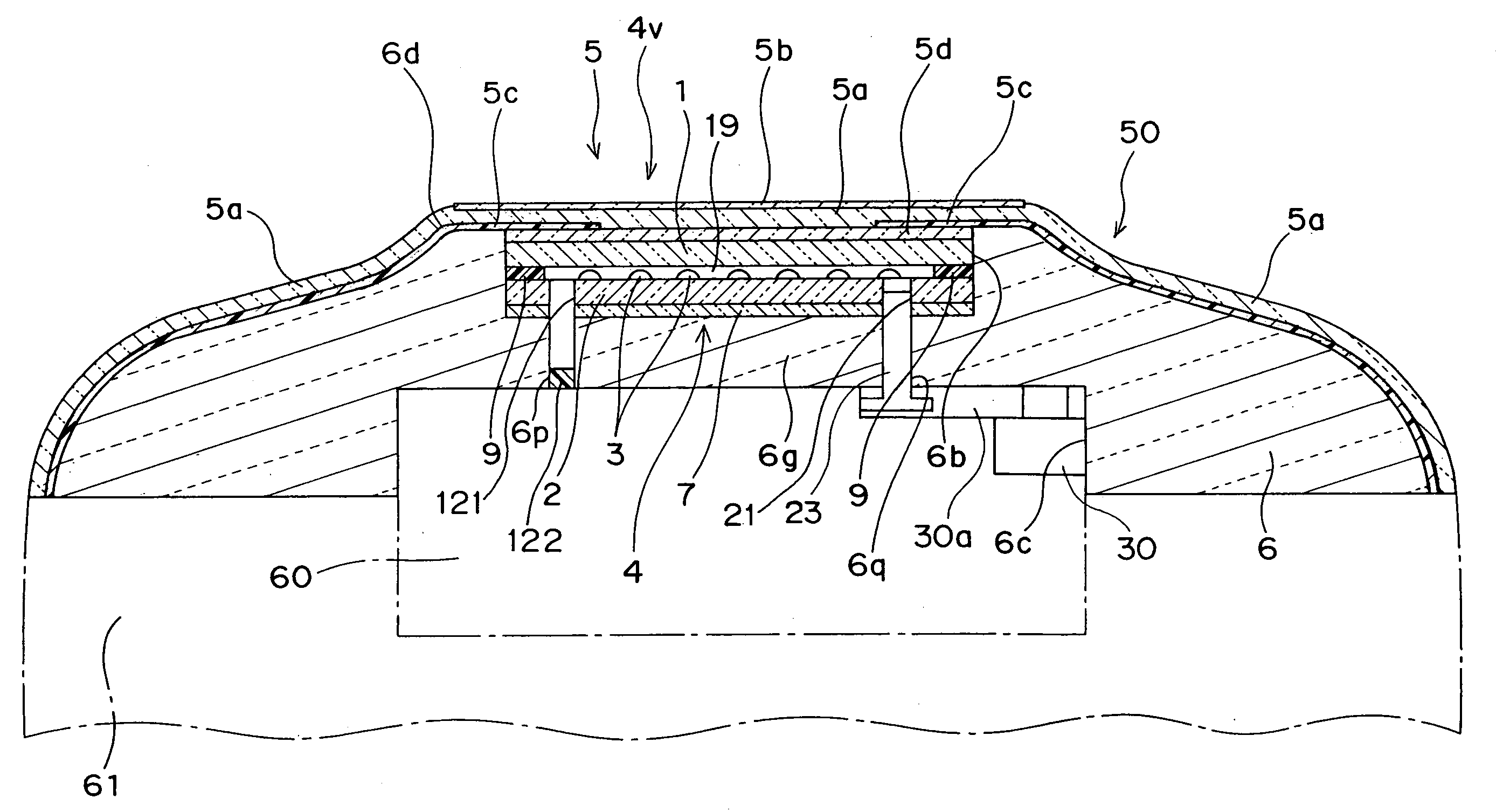
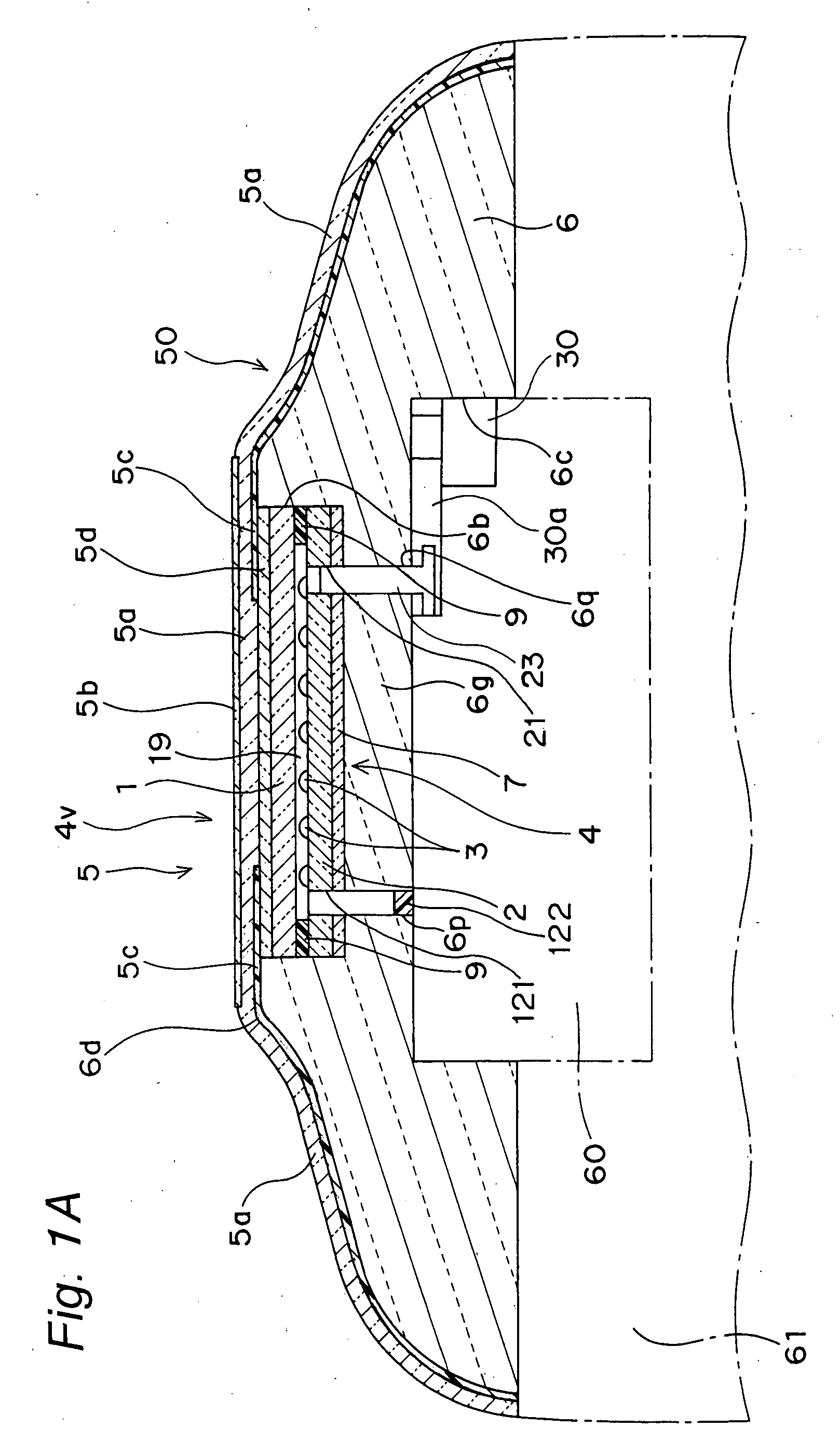
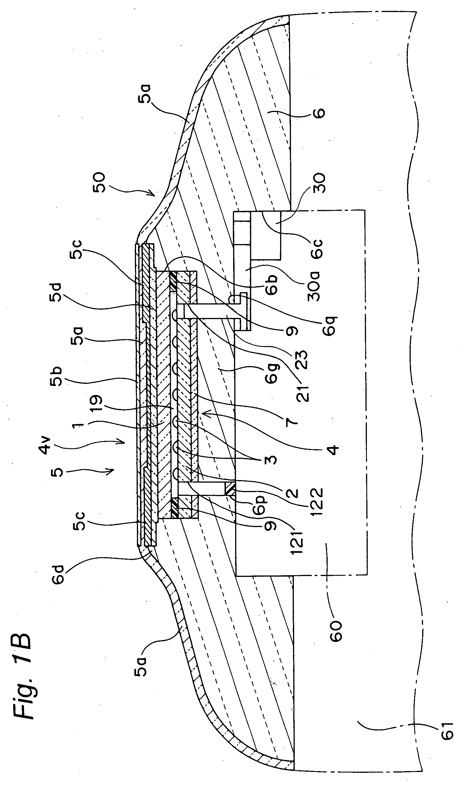
[0051]An integrally-molded touch panel unit according to the present invention is constituted by a touch panel 4, a design sheet 5 placed on the upper surface (the outer surface) of the touch panel 4, and a supporting plate-cum-casing 6 as an example of a touch-panel-unit casing placed around the design sheet 5, as illustrated in FIGS. 1A and 2A.

[0052]The touch panel 4 is a touch panel having a representational function and being capable of being mounted to a display unit such as a liquid crystal display of an electronic apparatus such as a cellular phone, a smart phone, a portable gaming machine, or a PDA. Further, the touch panel 4 is structured to include an upper electrode film 1 and a lower electrode film 2 which are placed such that their electrode surfaces are faced inwardly and they are opposed to each other with a plurality of insulation dot spacers 3 interposed therebetween, wherein the upper electrode film 1 and the lower electrode film 2 are attached to each other by a d...

second embodiment

[0092]For example, according to the present invention, there can be provided an integrally-molded touch panel unit having a flat lower surface 6j instead of the lower recessed portion 6c formed in the lower portion of the supporting plate-cum-casing 6, as illustrated in FIGS. 8A and 8B.

third embodiment

[0093]Also, according to the present invention, there can be provided an integrally-molded touch panel unit having a T-shaped through hole 6h formed by coupling the lower recessed portion 6c formed in the lower portion of the supporting plate-cum-casing 6 to the recessed portion 6b, as illustrated in FIGS. 9A and 9B. By fitting the display unit 60 in the T-shaped through hole 6h, it is possible to position, easily, the display unit 60 and the touch panel 4.

[0094]Further, the T-shaped through hole 6h is adapted to be communicated with a slot portion 6i formed in the lower surface of the touch panel unit along the longitudinal direction. Also, the T-shaped through hole 6h can be formed by hollowing out the supporting plate-cum-casing 6 only at the portion into which the display unit 60 is to be fitted.

[0095]In the integrally-molded touch panel unit according to the third embodiment, as illustrated in FIG. 10, four air holes 121 are preliminarily formed using a drill or a pressing mach...


PUM


Abstract

There are provided a design sheet (5) attached to the surface of an upper electrode film (1) of a touch panel (4) such that the design sheet is protruded at its periphery from the touch panel (4) and a touch-panel-unit casing (6) which is integrally molded with the design sheet (5) such that the casing is covered at its surface with the design sheet (5) and surrounds the side surfaces of the touch panel (4).

Description

TECHNICAL FIELD[0001]The present invention relates to a touch panel to be used as a coordinate inputting means and a pressed-position detection means and a touch panel unit including a panel for protecting a display window in an electronic apparatus employing the touch panel.BACKGROUND ART[0002]A touch panel having a displaying function which is incorporated in an electronic apparatus such as a cellular phone, a smart phone, or a PDA is mounted through the following method. That is, as illustrated in FIG. 16, a display unit 102 such as a liquid crystal display is fitted into a lower casing 101, then a touch panel 103 is attached to the display unit 102 at the peripheries of their surfaces or over their entire surfaces, thereafter the touch panel 103 is covered with an upper casing 104 having an opening portion 104a which defines the display area of the touch panel 103 while the periphery of the surface of the touch panel 103 is pressed by the upper casing 104 and, then, the upper ca...

Claims


Application Information

Patent Timeline
IPC IPC(8): G06F3/041
CPCG06F3/041H01H2207/008H01H2207/012H01H2209/002H01H2209/014H01H2209/082Y10S345/905H01H2219/03H01H2223/002H01H2223/014H01H2229/047H01H2229/062H01H2211/014G06F3/045G06F3/0412
Inventor NISHIKAWA, KAZUHIROASAKURA, TAKESHITSUCHIDA, NORIAKIHAMAOKA, KOICHI
Owner NISSHA PRINTING COMPANY
Why Eureka
Try Eureka