
Piezo-electric type page width inkjet printhead and image forming apparatus having the same

a technology of inkjet printhead and piezoelectric type, which is applied in the direction of printing, inking apparatus, other printing apparatus, etc., can solve the problems of increasing the manufacturing cost of array printhead, slow printing speed of shuttle type printhead, and inability to assemble printheads in terms of process, so as to achieve the effect of low manufacturing cos

Inactive Publication Date: 2008-06-12
SAMSUNG ELECTRO MECHANICS CO LTD
View PDF2 Cites 15 Cited by
  • Summary
  • Abstract
  • Description
  • Claims
  • Application Information

AI Technical Summary

Benefits of technology

[0014]The present general inventive concept provides a piezo-electric type page width inkjet printhead in which an integrated nozzle and circuit can be manufactured using a large-area process with low manufacturing costs, and an image forming apparatus having the same.

Problems solved by technology

Although the shuttle type printhead can realize color printing having high quality, a printing speed of the shuttle type printhead is slow.
However, it is difficult to assemble the printheads in terms of process, and thus, the manufacturing costs of the array print head increase.
However, in order to manufacture a large-area page width printhead, micromachining technology having a high degree of difficulty in terms of manufacturing is used.
Accordingly, the large-area page width printhead is costly.
A printhead is manufactured by using one chip having a diameter of eight inches or more, and thus, costs for assembling the printhead can not be removed.

Method used


Image

  • Piezo-electric type page width inkjet printhead and image forming apparatus having the same
  • Piezo-electric type page width inkjet printhead and image forming apparatus having the same
  • Piezo-electric type page width inkjet printhead and image forming apparatus having the same

Examples


Embodiment Construction

[0037]Reference will now be made in detail to the embodiments of the present general inventive concept, examples of which are illustrated in the accompanying drawings, wherein like reference numerals refer to the like elements throughout. The embodiments are described below in order to explain the present general inventive concept by referring to the figures.

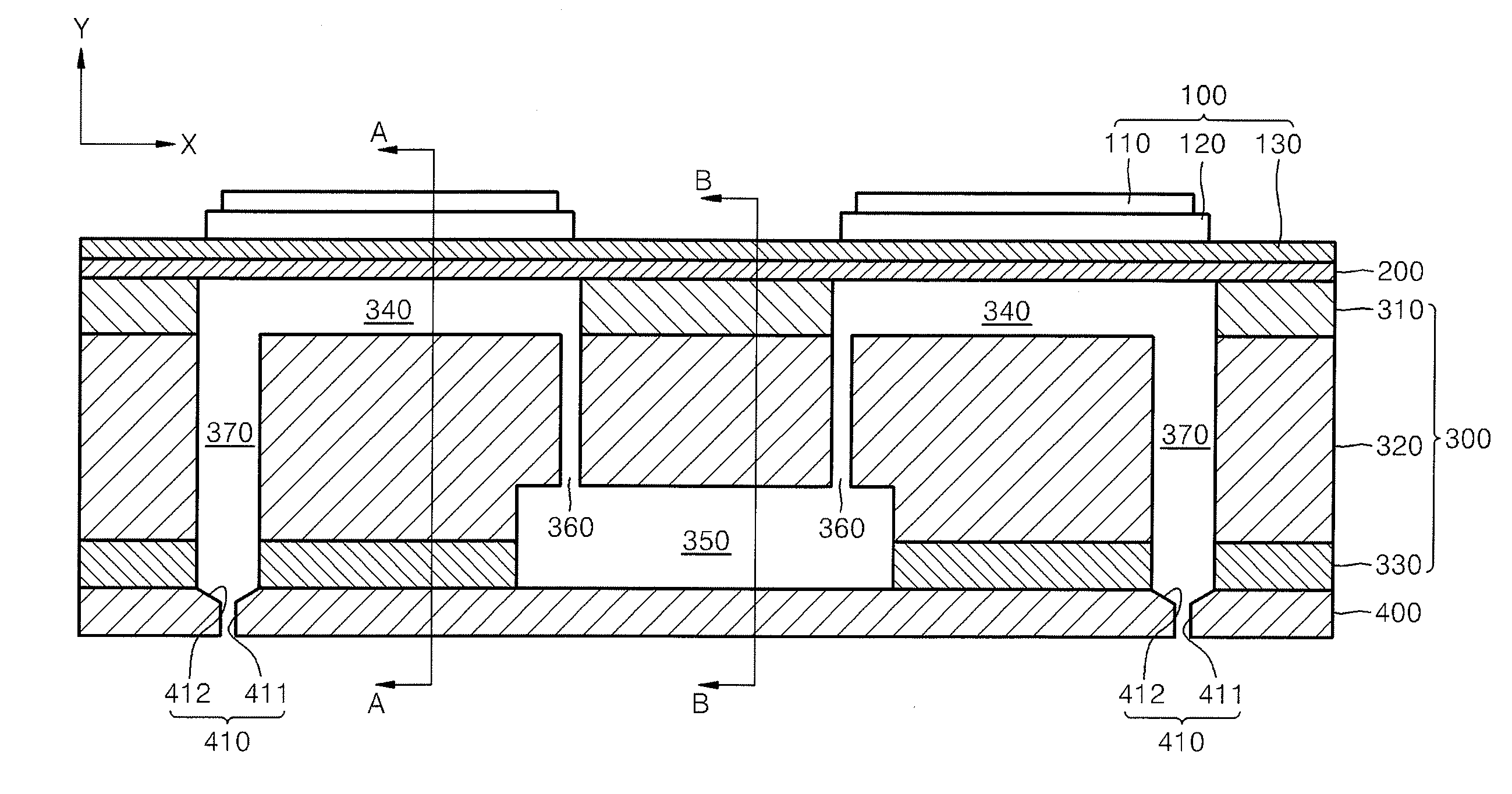
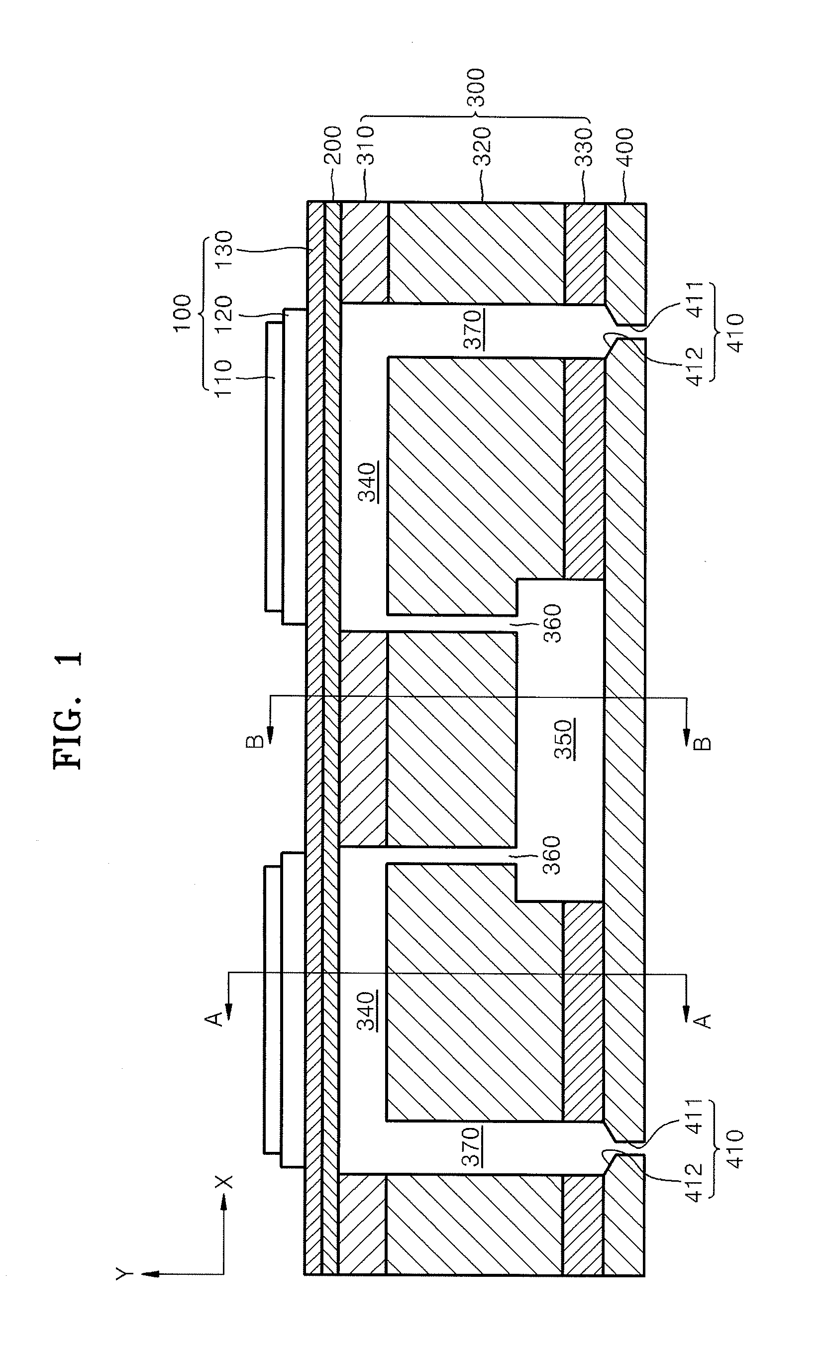
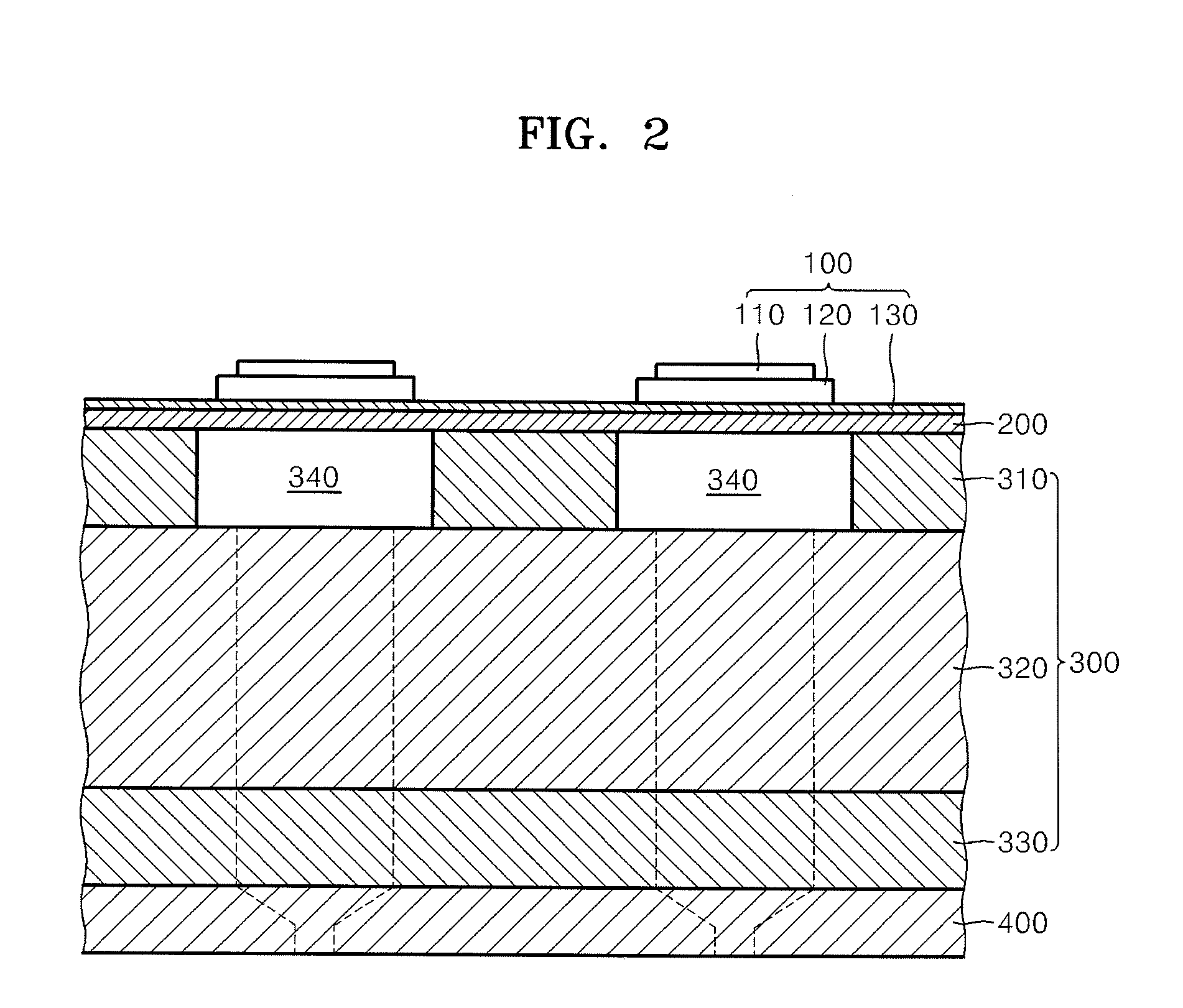
[0038]FIG. 1 is a cross-sectional view illustrating a piezo-electric type page width inkjet printhead taken along a lengthwise direction of a pressure chamber 340 thereof, according to an embodiment of the present general inventive concept. FIG. 2 is a cross-sectional view illustrating the piezo-electric type page width inkjet printhead taken along line A-A of FIG. 1.

[0039]FIG. 3 is a cross-sectional view illustrating the piezo-electric type page width inkjet printhead taken along line B-B of FIG. 1.

[0040]Referring to FIGS. 1, 2, and 3, the piezo-electric type page width inkjet printhead is configured by stacking and attaching u...


PUM


Abstract

A piezo-electric type page width inkjet printhead includes an intermediate substrate that includes a pressure chamber to be filled with ink to be ejected, a manifold connected to an ink entrance hole to store ink that flows in through the ink entrance hole, a restrictor to connect the manifold to one end of the pressure chamber, and a damper formed through the intermediate substrate corresponding to the other end of the pressure chamber, a lower substrate including a nozzle formed through a portion of the lower substrate, which corresponds to the damper, to eject the ink, an upper substrate formed on the intermediate substrate to seal an upper side of the pressure chamber, and a piezoelectric actuator formed on the upper substrate to generate a driving power to the pressure chamber to eject the ink through the nozzle, wherein the intermediate substrate comprises a both-sided copper clad laminate plate comprising an upper copper film and a lower copper film that are respectively formed on top and bottom surfaces of the laminate plate.

Description

CROSS-REFERENCE TO RELATED APPLICATIONS[0001]This application claims the benefit of Korean Patent Application No. 10-2006-0126411, filed on Dec. 12, 2006, in the Korean Intellectual Property Office, the disclosure of which is incorporated herein in its entirety by reference.BACKGROUND OF THE INVENTION[0002]1. Field of the Invention[0003]The present general inventive concept relates to a piezo-electric type page width inkjet printhead, and more particularly, to a piezo-electric type page width inkjet printhead in which a copper clad laminate (CCL) substrate is used, and an image forming apparatus having the same.[0004]2. Description of the Related Art[0005]Generally, an inkjet printhead or a shuttle type printhead (hereinafter referred to as ‘shuttle type printhead’) is spaced a predetermined distance from a top surface of a sheet of paper. The shuttle type printhead forms an image on the paper by ejecting ink onto the paper while reciprocating in a perpendicular direction (the width...

Claims


Application Information

Patent Timeline
IPC IPC(8): B41J2/045B41J29/38
CPCB41J2/055B41J2202/11B41J2002/14419B41J2/14233B41J2/045
Inventor BAEK, SEOK-SOONSHIN, SEUNG-JOOKIM, SEONG-JIN
Owner SAMSUNG ELECTRO MECHANICS CO LTD
Learn More