Eye tracker/head tracker/camera tracker controlled camera/weapon positioner control system

a technology of head tracker and control system, which is applied in the field of system and method of tracking a target, can solve the problems of system inherently limited field of view, inability to provide parallax vision, and too far a device in an attempt to replicate human vision

Inactive Publication Date: 2008-06-12
WOLFF ROBIN QUINCEY
View PDF3 Cites 203 Cited by
  • Summary
  • Abstract
  • Description
  • Claims
  • Application Information

AI Technical Summary

Benefits of technology

[0014]The orbital positioning night vision devices may allow the user to view the scene around him at night using his natural eye movements instead of having to move his head in order to see a limited field of view. It also may allow the user to view the scene with peripheral vision that is limited by the optics and helmet design.
[0015]In yet another embodiment, the orbital positioning device mounted camera may allow the user to view the scene around him via a display. The display may produce a parallax view as is produced by the orbital positioning system which provides dual image signals mimicking the human visual system. This system may more readily produce a 3D image that replicates that of a human being because it positions optical devices at the same angles that the user's eyes use to view the image, in real-time, by tracking the user's eye movements and using the tracking data to independently control camera positioning devices that maneuver the cameras at an equal distance from the center of each of the user's eyes on any point within the user's field of view.

Problems solved by technology

While these systems can position a device, even on an unstable platform, they usually require a second person to control other features of a camera, such as the focus and zoom motors that position the adjustment rings on camera.
These devices either go too far in an attempt to replicate human vision or not far enough.
These systems are inherently limited in the field of view they provide because of the limited maneuverability of the tube mounts.
Later systems, such as Moody, in U.S. Pat. No. 6,462,894, place four intensifier tubes in pairs to give the user a wider field of view, but they still require that the user must move his head in order to look in a certain direction, especially up and down, and do not provide for parallax vision.
Designers have also attempted to mount cameras on the head of a user in different configurations, but none have replicated the human parallax vision system.

Method used


Image

  • Eye tracker/head tracker/camera tracker controlled camera/weapon positioner control system
  • Eye tracker/head tracker/camera tracker controlled camera/weapon positioner control system
  • Eye tracker/head tracker/camera tracker controlled camera/weapon positioner control system

Examples


Embodiment Construction

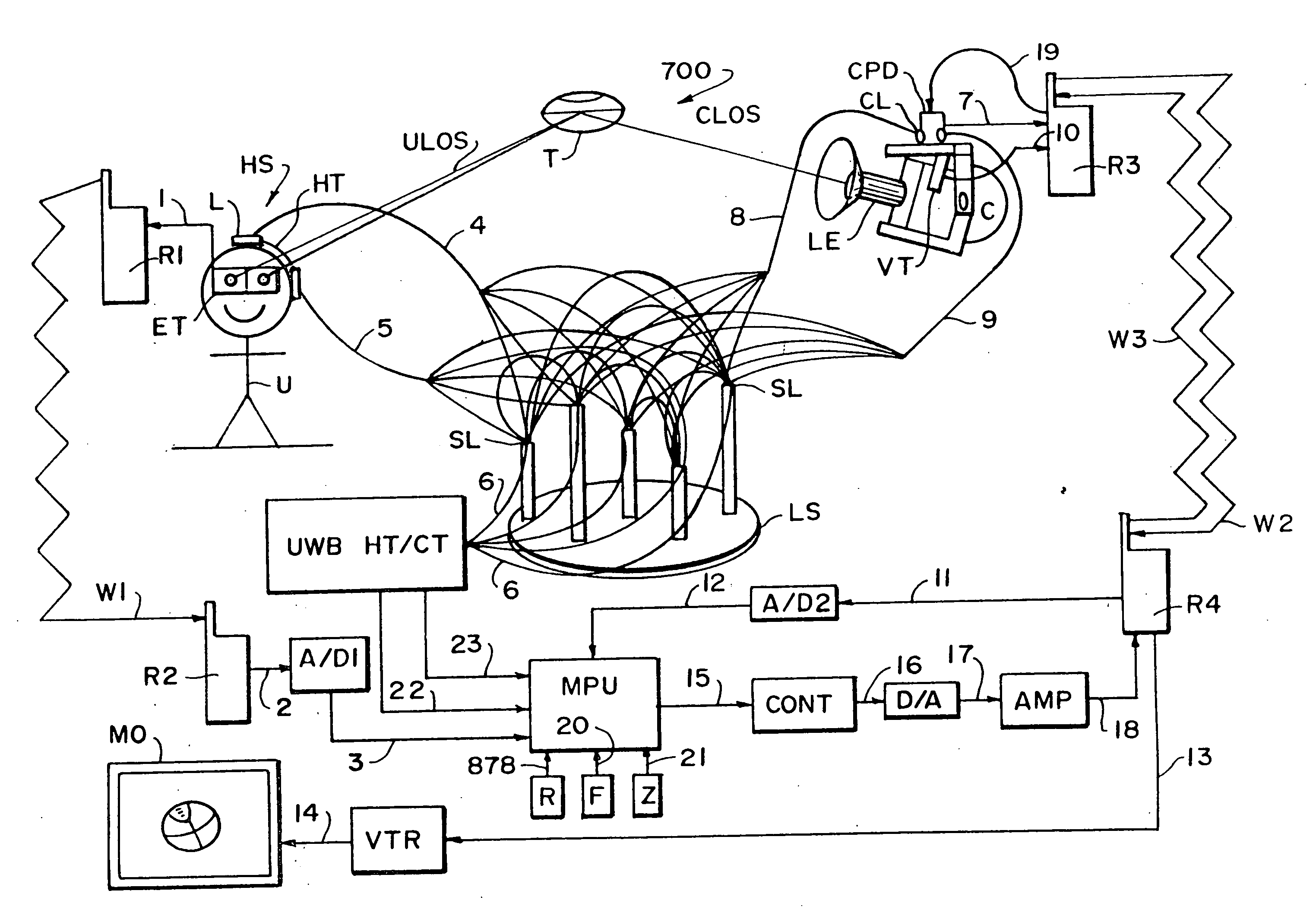
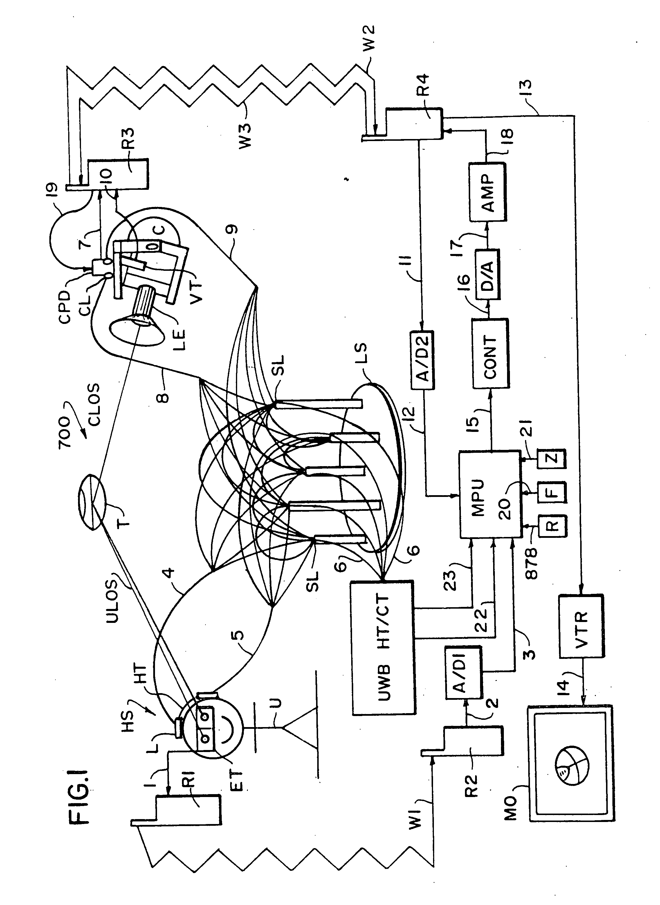
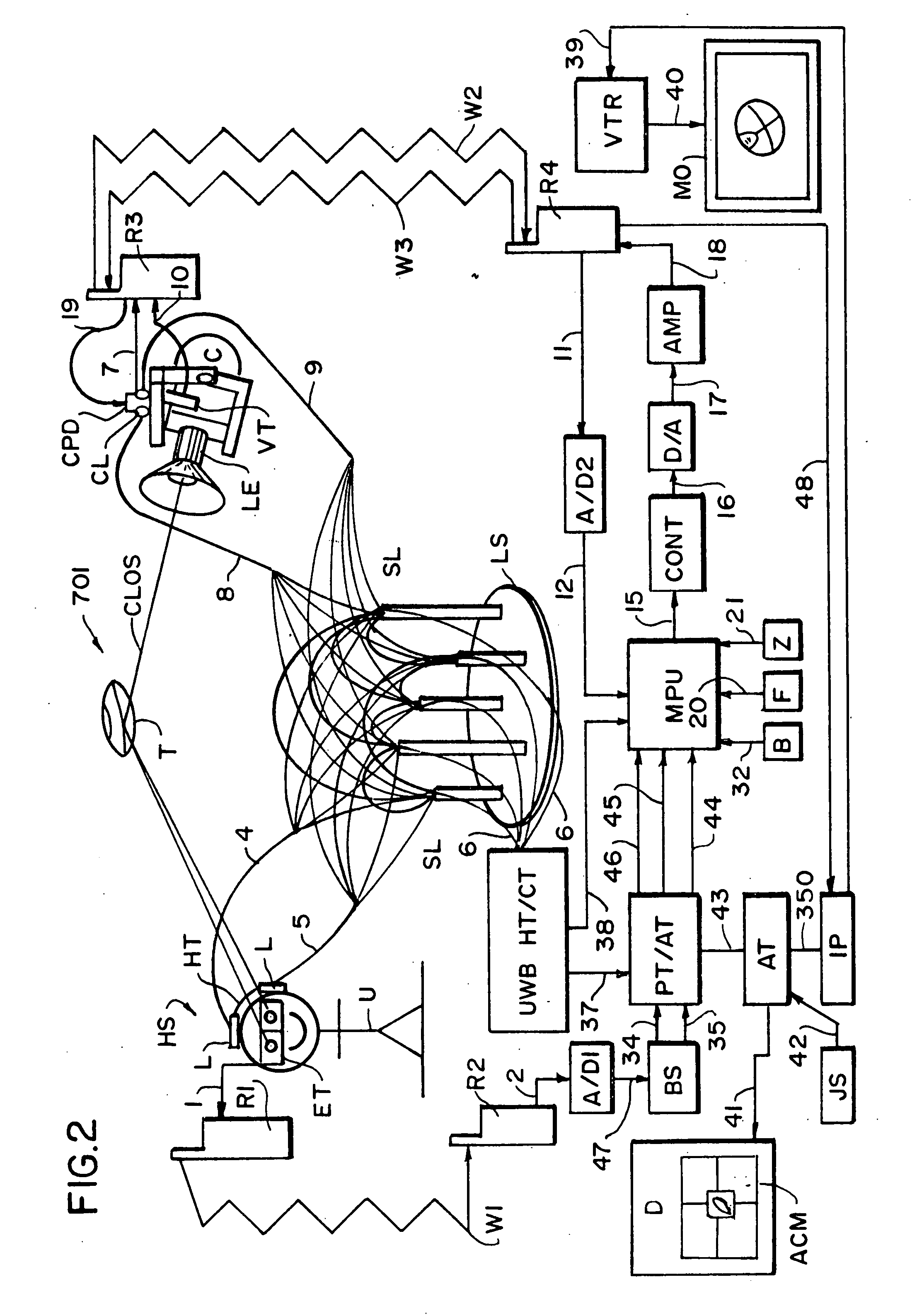
[0072]Throughout the specification, similar devices and signals are identified with the same identification indicia.

[0073]This invention is directed to a tracking system of the type used by a human user. There is provided eye tracking means for tracking the dynamic orientation of the eyes of the user (i.e., the orientation of the eyes in three dimensions with respect to the head). Head tracking means are provided for tracking the dynamic orientation of the head of the user (i.e., the orientation and position of the head in three dimensions in space). At least one positioning device (e.g., a tilt and pan head, a rotary table, or the like) is also provided. There are also provided means for tracking the dynamic orientation of the positioning device (i.e., the orientation and position of the positioning device in space). The eye tracking, head tracking, and positioning device tracking means provide signals to a computer processor from which the eyes of the user directs the position dev...


PUM


Abstract

A user has both a head tracker and eye tracker sending signals to a processor to determine the point of view of the user. The processor also receives signals indicative of the point of view of a camera, weapon or laser target designator. The microprocessor compares the two points of view and sends instructions to the camera, weapon or laser target designator to adjust its position to align the points of view. In another embodiment the optical devices are supported on orbital tracks attached to a helmet. The optical devices are fully mobile to follow the user's eyes through any_movement. The helmet mounted system can automatically adjust for any user and has a counterweight to balance the front armature.

Description

FIELD OF THE INVENTION[0001]The invention relates to a system and method for tracking a target and related devices and systems.BACKGROUND OF THE INVENTION[0002]Systems permitting the user to remotely operate a camera have become commonplace in the film and video production industry during the last decade, such as disclosed in U.S. Pat. No. 4,683,770 (Nettmann). Other systems allow a camera to be remotely operated mounted to an unstable vehicle by counteracting g-forces using gyroscopes disclosed in U.S. Pat. No. 4,989,466 (Goodman). Systems providing teleoperation of weapons have been documented in use since 1915 when Australian Lance Corporal W. C. B. Beech invented the “Sniperscope.” This concept was used by Rowe (Design Pat. No. 398,035), and has been further automated by Hawkes et al. (U.S. Pat. Nos. 6,237,462 and 6,269,730).[0003]These systems allow the user to position and operate a camera or weapon from a remote location, but they require the user to manipulate the aiming con...

Claims


Application Information

Patent Timeline
Patent Type & Authority Applications(United States)
IPC IPC(8): G06K9/00G06F3/033H04N5/225
CPCG06F3/012H04N5/232G06F3/013H04N23/67H04N23/61H04N23/63
Inventor WOLFF, ROBIN QUINCEY
Owner WOLFF ROBIN QUINCEY
Why Eureka
Try Eureka