Apparatus for Projecting Video Image and Method Thereof

a technology for projectors and video images, applied in the direction of picture reproducers using projection devices, color television details, television systems, etc., can solve the problems of large weight and bulk, inconvenient use, and inability to carry and carry, and achieve the difficulty of manufacturing lcd projectors. the effect of easy operation

Inactive Publication Date: 2008-06-12
YUAN NING +1
View PDF11 Cites 4 Cited by
  • Summary
  • Abstract
  • Description
  • Claims
  • Application Information

AI Technical Summary

Benefits of technology

[0008]The present invention provides an apparatus for projecting video image, comprising an interface for receiving video input signals inclusive of video signals and synchronization signals; a CPU for producing various kinds of control signals in accordance with the synchronization signals from the interface; a signal converting unit for converting the video input signals to digital video data streams in accordance with the controls signals from the CPU; a First-in First-out memory unit for receiving and temporarily storing digital video signals from the signal converting unit, converting said digital video signals to video data streams with time character in accordance with the control signals from the CPU, and outputting the video data streams with time character under control of the CPU; a serial / parallel converting unit for receiving the video data streams with time character from the First-in First-out memory unit in accordance with the control signals from the CPU and serial / parallel converting them to parallel video data streams; three primary colors or multiple primary colors emitting diode lines comprising a plurality of three primary colors or multiple primary colors emitting diode units, for causing the corresponding three primary colors or multiple primary colors emitting diodes units to emit light under the excitation of the parallel video data streams, so as to produce color visible light of various different color combinations; convergent lens lines comprising a convergent lens configured at a luminous terminal of each of the three primary colors or multiple primary colors emitting diode units, for focusing the color visible light produced by each of the three primary colors or multiple primary colors emitting diode units to form color visible light lines; lumen emitting diode units for controlling illuminating one to plural sets of lumen emitting diodes to produce lumen visible light in accordance with the control signals of the CPU, based on the conditions required by different lumen illuminations; a light beam lens for receiving mixed color visible light for ed by the color visible light lines and the lumen visible light, the mixed color visible light penetrating the light beam lens and subjected to parallel processing; a light beam slit having a slit of a predetermined width for performing parallel processing of the mixed color visible light and constraining it to narrow bars; a mirror surface triple prism or a mirror surface multiprism, driven by an electric machine to synchronously rotate, for receiving the mixed color visible light in narrow bars at a constantly variable incidence angle and reflecting it; a negative lens (1-7) for receiving the mixed color visible light in narrow bars reflected by the mirror surface triple prism or mirror surface multiprism, the mixed color visible light penetrating the negative lens and being transversely diffused, the negative lens having a curvature that meets the requirements for forming a visible color video image by the mixed color visible light, so that the mixed color visible light is uniformly diffused in a single direction and projected on the screen; the incidence angle at which the continuous mixed color visible light produced under the effect of the parallel video data streams and lumen control signals irradiates a mirror surface of the mirror surface triple prism or mirror surface multiprism varies at a constant speed in a constant direction, so does a reflection angle of the corresponding mixed color visible light. Thus, different positions on a certain plane irradiated by the continuous mixed color visible light reflected produce lines composed of light spots of the continuous mixed color visible light parallel with the turning direction of the mirror surface triple prism or mirror surface multiprism and the lines composed of continuous light spots constitute each line of the color video image, thereby forming a visible video image; when the mirror surface triple prism or mirror surface multiprism is rotated to an angle contained by respective mirror surfaces, the First-in First-out memory chip is controlled to stop the output of data streams with time character, namely, controlling the corresponding three primary colors or multiple primary colors emitting diode units to stop irradiation, while when the mirror surface triple prism or mirror surface multiprism is rotated to a starting end of the next mirror surface, the First-in First-out memory chip is controlled to start the output of data streams with time character, namely, controlling the corresponding three primary colors or multiple primary colors emitting diode units to start irradiation, and the reflection produced by the continuous mixed color visible light forms a next visible light video image, and iteratively doing so, a continuous dynamic color visible picture provided by the received analog signal data streams is thus formed.

Problems solved by technology

Moreover, the CRT projectors have a large weight and bulk, so they are not portable and cannot be conveniently used.
Thus, the difficulty of the technique of manufacturing the LCD projectors may be well imagined
There are also the projectors made of two-piece or three-piece DMD chips, whose brightness may achieve 1-200ANSI lumen, and these projectors can randomly zoom and be conveniently adjusted, but they have high costs.
According to the above description of the CRT projectors, LCD projectors and DLP projectors, these three types of projectors are common in having large power consumption, needing a blower heat dissipation system and a high-power lumen system and the like, being realized with technical difficulties, taking high costs, and having large bulk and great weight.

Method used


Image

  • Apparatus for Projecting Video Image and Method Thereof
  • Apparatus for Projecting Video Image and Method Thereof
  • Apparatus for Projecting Video Image and Method Thereof

Examples


Embodiment Construction

[0046]The signals received by the apparatus for projecting video image according to the present invention can be analog RGB video data streams, analog CVBS video data streams, S-VIDEO video data streams, DVD video data streams and the like. Thus, the apparatus for projecting video image first utilizes different processing chips to convert analog video signals and non-24-bit RGB digital video signals to 24-bit digital RBG video signals, i.e., the digital RGB video data streams with ED, GREEN and Blue in 8 bits, respectively.

[0047]Detailed description is made with reference to FIG. 13 by taking as an example converting analog RGB video signals to 24-bit digital D-RGB video data streams.

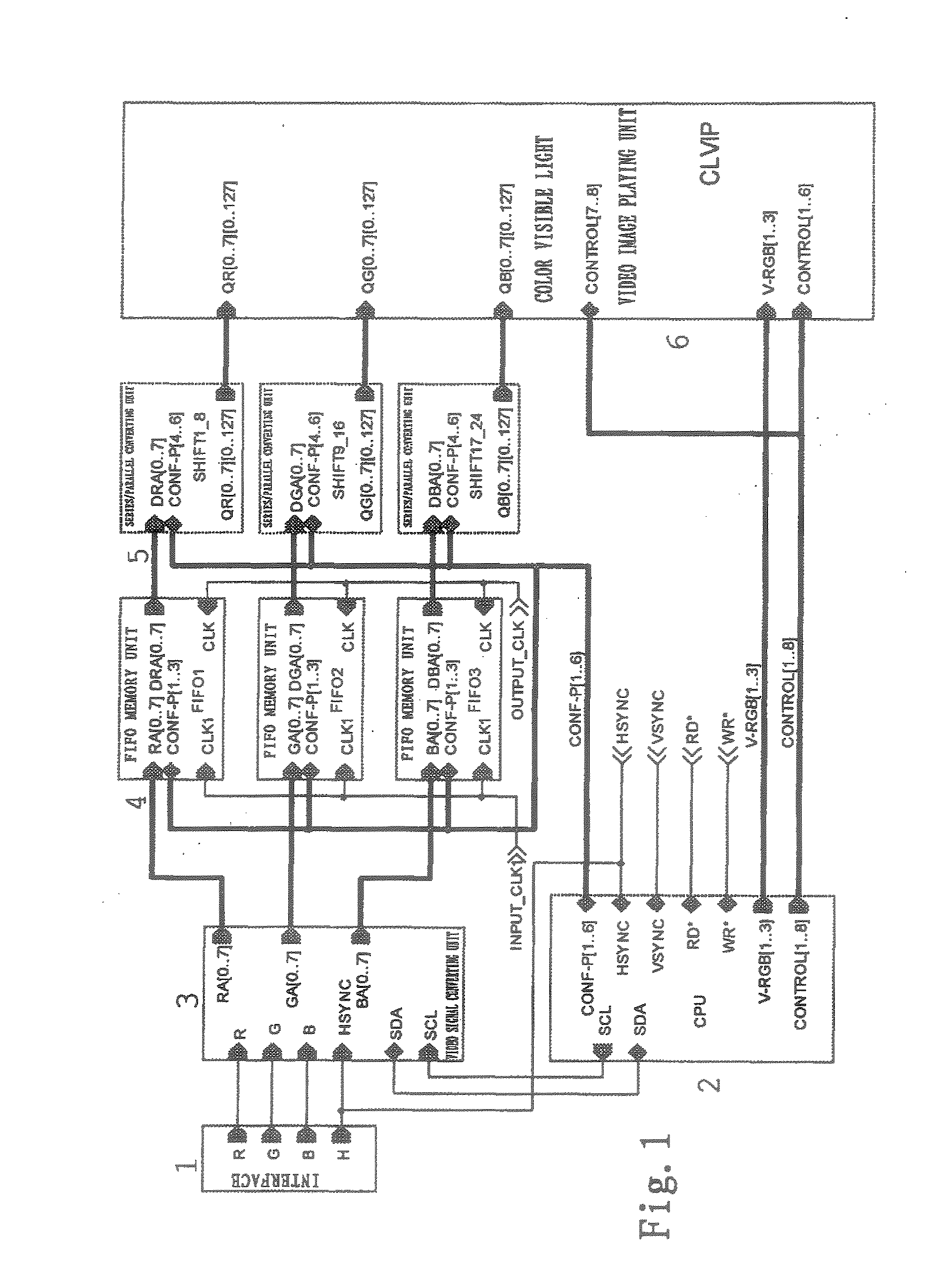
[0048]FIG. 1 is a schematic circuit diagram of the apparatus for projecting video image according to the present invention, wherein an interface 1 (P1, FIG. 7) receives the analog RGB video signals inclusive of RED (R), GREEN (G) and BLUE (B) signals, horizontal synchronization signals HSYNC and vertica...


PUM


Abstract

An apparatus for projecting video image comprises a CPU for producing all kinds of control signals, a signal converting circuit, a Firstin First-out memory unit for converting the digital video signal streams into the video signal streams with time character, a serial/parallel converting unit and a playing unit for playing video image of color visible light. The apparatus also comprises three primary colors emitting diode lines for producing color visible light, convergent lens lines for converging color visible light, lumen emitting diode element, light beam lens, light beam slit, mirror surface triple prism or mirror surface multiprism for receiving and reflecting the mixed color visible light and negative lens for receiving single direction diffuseness of mixed color visible light and projecting on the screen, so that the received analog singal streams can product sequential dynamic color visible picture. The apparatus for projecting video image of the present invention is portable and has low power loss and low cost. The definition of projection and the lumen illumination are improved and the electromagnetic noise is reduced by utilizing the present invention. The present invention also relates to the method for projecting video image.

Description

FIELD OF TECHNOLOGY[0001]The present invention generally relates to an apparatus for processing video image and a method thereof and particularly relates to a method for projecting video image and a method thereof.BACKGROUND ART[0002]The currently used projecting devices mainly comprise Cathode-ray Tube (CRT) projectors, LCD projectors, DLP projectors and so forth.[0003]The CRT projectors provide RGB analog signals to cathode-ray tubes to emit light under high voltage and through signal amplification and convergence, color images are displayed on a screen. The images projected by the CRT projectors have good picture restoration and good colors, but the machines have a low luminance and need to be debugged by the technicians for use. Moreover, the CRT projectors have a large weight and bulk, so they are not portable and cannot be conveniently used. To accomplish the optimum image convergence, the CRT projectors are required to have a good correcting function for distortions in plural...

Claims


Application Information

Patent Timeline
Patent Type & Authority Applications(United States)
IPC IPC(8): H04N9/31
CPCH04N9/3129H04N9/31
Inventor YUAN, NINGZHANG, LI
Owner YUAN NING
Why Eureka
Try Eureka