Light Guide Plate, and Planar Lighting Device and Liquid Crystal Display Device Using Such Light Guide Plate

a technology of light guide plate and which is applied in the direction of planar/plate-like light guide, lighting and heating apparatus, instruments, etc., can solve the problems of limiting the thickness of liquid crystal display device, entanglement of power consumption, and shortcoming of light use efficiency, so as to enhance light use efficiency and reduce unevenness. , the effect of enhancing uniformity

Inactive Publication Date: 2008-06-12
FUJIFILM CORP
View PDF10 Cites 54 Cited by
  • Summary
  • Abstract
  • Description
  • Claims
  • Application Information

AI Technical Summary

Benefits of technology

[0068]According to the first aspect of the present invention, the light guide plate can be made thinner and more lightweight, and illumination light with an enhanced light use efficiency (light emitting efficiency) and an enhanced uniformity, hence a reduced unevenness, can be emitted from its light emitting plane.
[0069]Further, according to the first embodiment of the first aspect of the present invention, the peak of the illuminance or the brightness can be reduced whereas uniformity in illuminance or brightness on the light emitting plane can be enhanced so that the brightness distribution can be brought still closer to a flat distribution by tapering the sectional shape of the parallel groove in the direction of the peak end portion toward the light emitting plane according to the ratio of the peak of the illuminance or the brightness produced by light emitted from the rod-type light source accommodated in the parallel groove in the first portion of the light emitting plane corresponding to the parallel groove to the average value of the illuminance or the brightness in other areas. Further, the light use efficiency (light emitting efficiency) can be enhanced, and a high uniformity and a high light emitting efficiency required of the light emitting plane can be achieved by inclining the base end portion to a greater degree, e.g., more acutely, in cross section than the peak end portion.
[

Problems solved by technology

However, there was a limit to how thin a liquid crystal display device could be made because of unevenness in light amount distribution that occurred when the thickness of a backlight unit of the direct illumination type mentioned above used therein was reduced

Method used


Image

  • Light Guide Plate, and Planar Lighting Device and Liquid Crystal Display Device Using Such Light Guide Plate
  • Light Guide Plate, and Planar Lighting Device and Liquid Crystal Display Device Using Such Light Guide Plate
  • Light Guide Plate, and Planar Lighting Device and Liquid Crystal Display Device Using Such Light Guide Plate

Examples


Embodiment Construction

[0149]Now, detailed description will be made of the inventive light guide plate and the planar lighting device and the liquid crystal display device using the light guide plate based on preferred aspects given in the accompanying drawings.

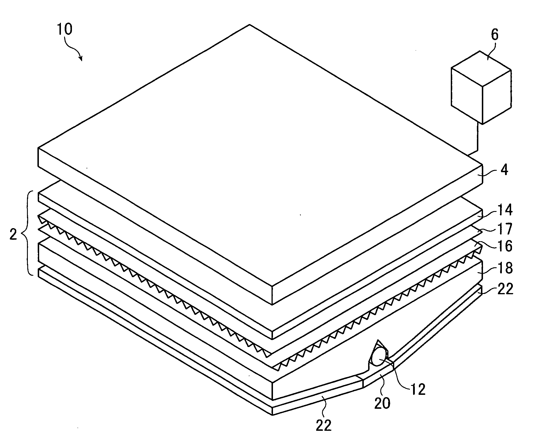
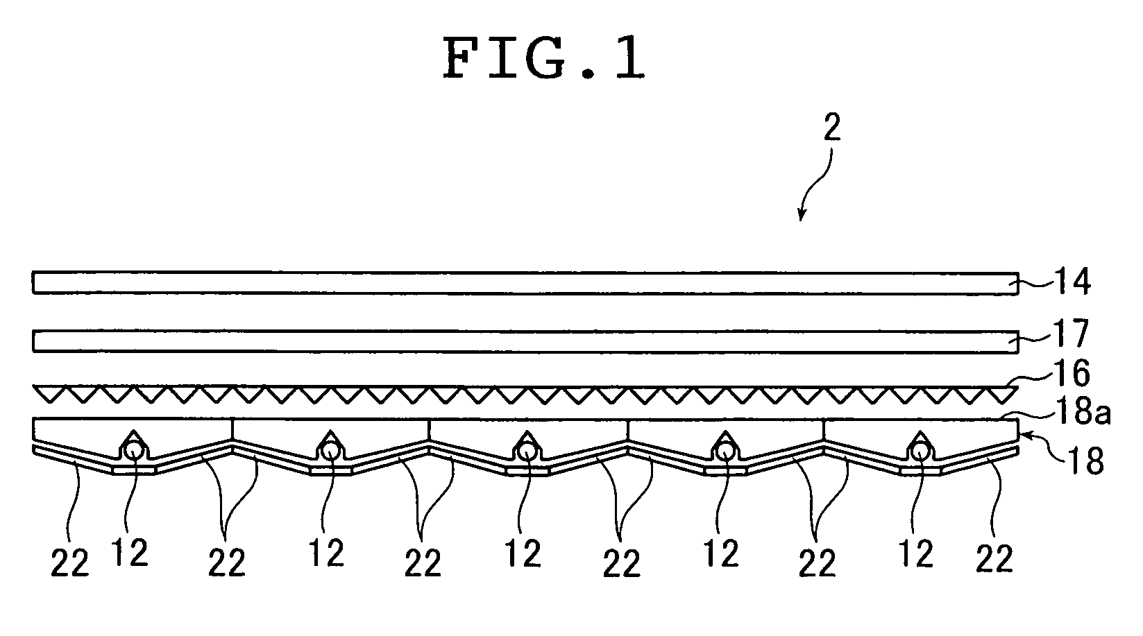
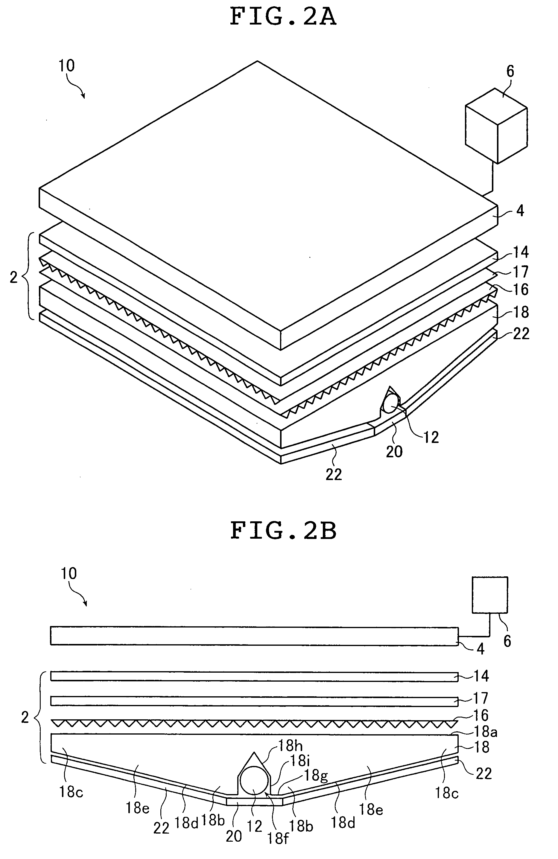
[0150]FIG. 1 illustrates a schematic sectional view of a planar lighting device 2 (referred to also as backlight below) according to the second aspect of the present invention formed by arranging a plurality of light guide plates 18 according to the first aspect of the present invention. The planar lighting device 2 as shown is used as a backlight unit for the liquid crystal display device according to the third aspect of the present invention. FIGS. 2A and 2B are schematic partial perspective and a schematic partial cross section illustrating one light guide plate 18 from the backlight unit 2 shown in FIG. 1 and a liquid crystal display device 10 using the backlight unit 2. As illustrated in FIGS. 2A and 2B, the liquid crystal display device 10 ba...


PUM


Abstract

A parallel groove of a light guide place for accommodating a light source has, in a perpendicular cross section, a shape composed of a pair of contour lines that approach each other toward a light emitting plane, cross at a peak, and has a part where an inclination angle to a line vertical to the light emitting plane changes, and the inclination angle at a base end side far from the peak is sharper than that at a tip end side close to the peak. Thus, uniform and high brightness light can be emitted.

Description

TECHNICAL FIELD[0001]The present invention relates to a transparent light guide plate for diffusing light admitted from rod-type light sources in a direction substantially parallel to a light emitting plane and emitting an illumination light with an enhanced uniformity from the light emitting plane and a planar lighting device and a liquid crystal display device using said light guide plate.BACKGROUND ART[0002]A liquid crystal display device uses a backlight unit to illuminate its liquid crystal panel (LCD) from the rear side of the liquid crystal panel.[0003]Currently, large liquid crystal display televisions predominantly use a backlight unit of a type called a direct illumination type (see JP 05-4133 U, for example). A backlight unit of direct illumination type has a plurality of cold cathode tubes provided behind the rear side of the liquid crystal panel as light sources to illuminate the liquid crystal panel; the inside of a housing in which the cold cathode tubes are arranged ...

Claims


Application Information

Patent Timeline
IPC IPC(8): F21V13/04F21V8/00G02F1/13357
CPCG02B6/0021G02B6/0031G02B6/005G02F1/133611G02B6/0068G02B6/0071G02B6/0055
Inventor IWASAKI, OSAMUMATSUSHITA, MOTOHIKOOKUMURA, TAKAMITSUENDO, TOSHIAKI
Owner FUJIFILM CORP
Why Eureka
Try Eureka