
Distributed message routing in a virtualized messaging system using recursive least squares links cost estimation with choke points

a virtualized messaging and cost estimation technology, applied in data switching networks, frequency-division multiplexes, instruments, etc., can solve problems such as race conditions, limited bandwidth for processing messages, and well-known performance issues of technique alone, so as to minimize round trip message latency, efficient and scalable

Active Publication Date: 2008-06-12
TWITTER INC
View PDF8 Cites 7 Cited by
  • Summary
  • Abstract
  • Description
  • Claims
  • Application Information

AI Technical Summary

Benefits of technology

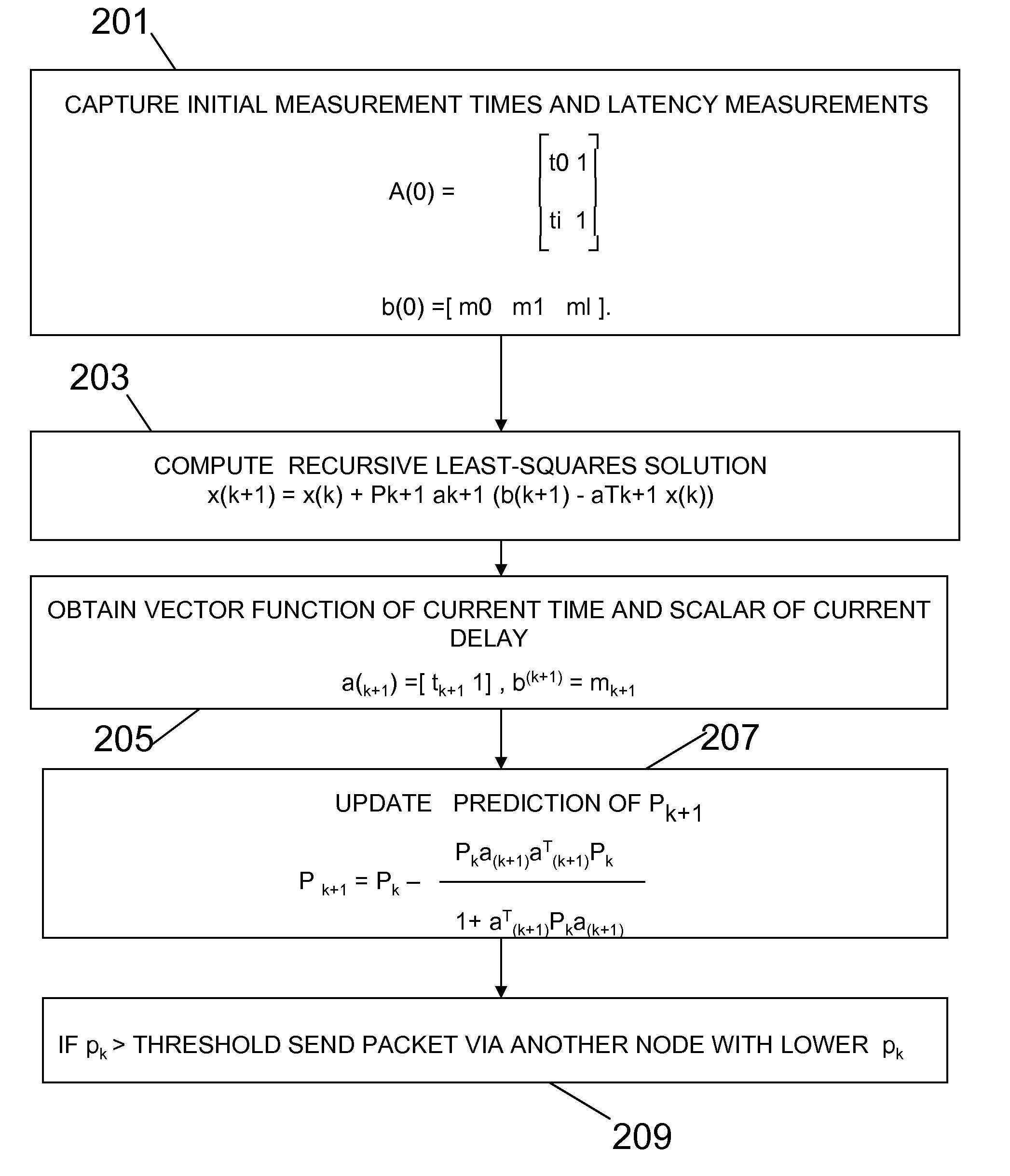
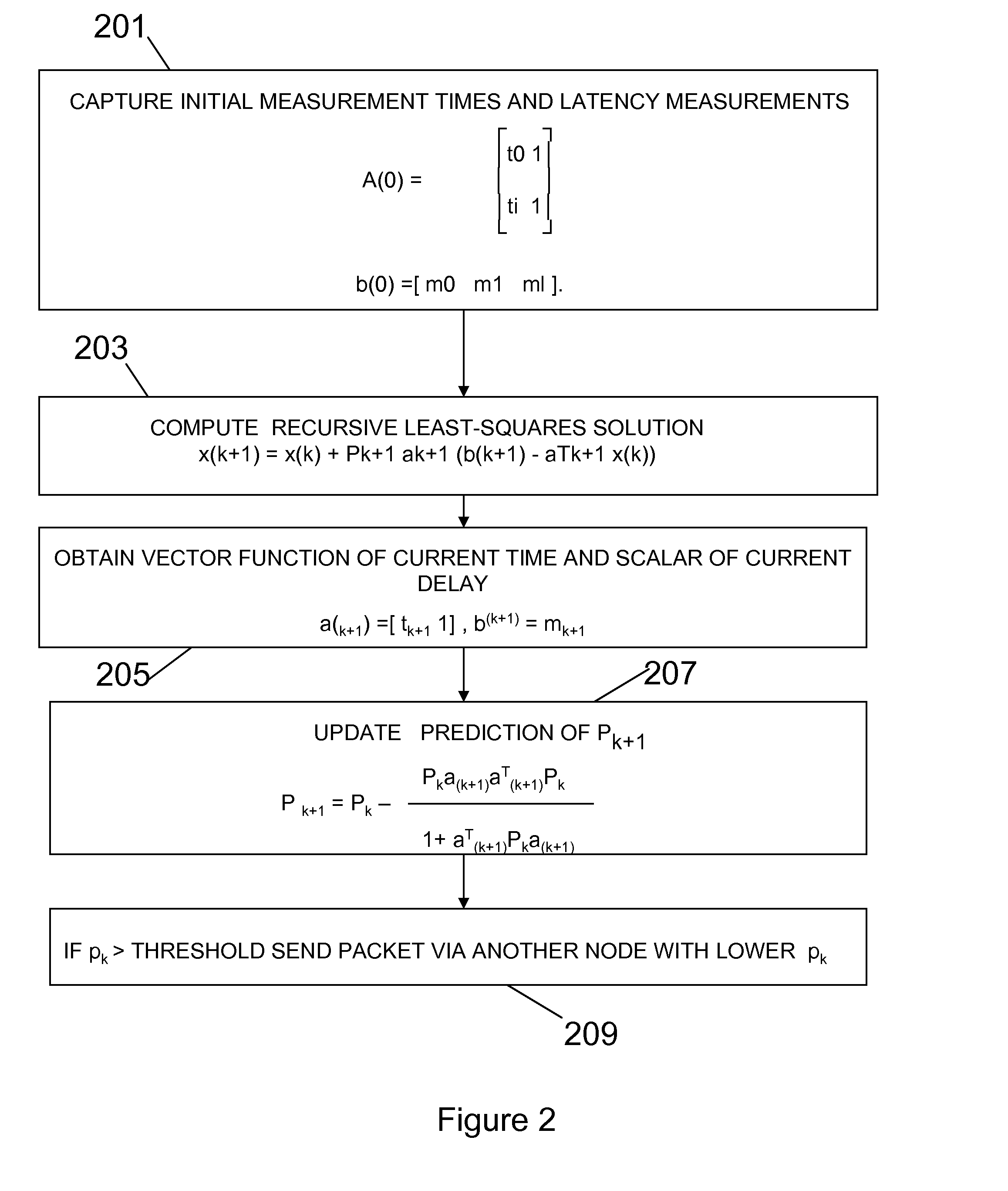
[0017]We avoid problems of the prior art by providing a distributed scheduling procedure for minimizing round trip message latency through a network of servers in a virtualized Message-Oriented Middleware (MOM) system, using a recursive least-squares prediction model for estimating the message latency in a virtualized MOM environment. Further, we utilize choke packets in the messaging layer to provide congestion control to the virtualized MOM environment that is directly compatible with the basic message latency estimation technique. This estimation procedure is then used by the distributed message routers to select nodes in the MOM on a per message basis that will minimize message latency without introducing a single point of failure to the virtualized MOM. This solution provides a more efficient and scalable means of effectively implementing a virtualized message bus.
[0018]Specifically, the problems associated with node congestion are avoided by routing message packets from one node in a network to another node by using message latency predictions to guide future message transfers and augmenting the predictions with direct node feedback in the form of choke packets used to correct anomalous behavior within the network. According to our invention the latency through a node for a subsequent packet is predicted using a well known recursive least squares procedure. The recursive least squares procedure attempts to fit a linear model to past message latency measurements to predict future message latencies for a next packet through each of the attached nodes.

Problems solved by technology

Each individual node is capable of delivering the entire ESB, but with limited bandwidth for processing messages.
The general problem then becomes how to implement a message routing heuristic that minimizes message latency without compromising reliability or scalability.
This technique alone is well known to have performance issues.
When each router utilizes a SPF approach then a race condition can occur when the network is under high load.
The result is that the under-utilized link quickly becomes overwhelmed causing network traffic to be routed away from that link and an oscillation occurs that degrades network performance.

Method used


Image

  • Distributed message routing in a virtualized messaging system using recursive least squares links cost estimation with choke points
  • Distributed message routing in a virtualized messaging system using recursive least squares links cost estimation with choke points
  • Distributed message routing in a virtualized messaging system using recursive least squares links cost estimation with choke points

Examples


Embodiment Construction

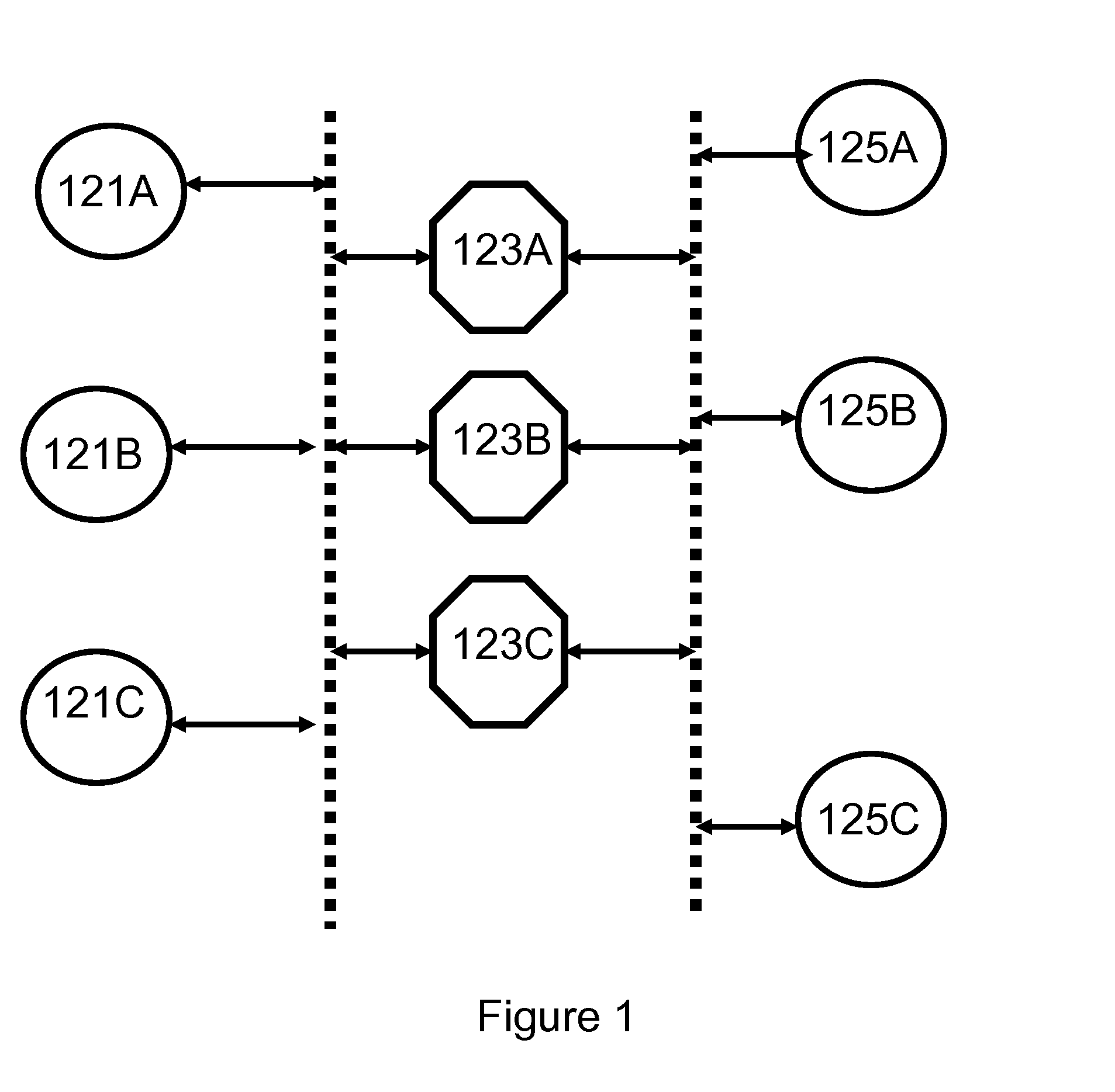
[0024]The invention described herein controls routing of message packets from one node, e.g., a requester node, in a network to another node, e.g., a provider node in the network, through the network from the requester node, i.e., the origin node to a provider node, i.e., the destination node using a chosen path through the network. FIG. 1 is a high level schematic diagram of a packet network 101 with nodes, including requester nodes 121A, 121B, and 121C associated with Routing Agent Software, and provider nodes 125A, 125B, and 125C, and ESB nodes as intermediate nodes 123A, 123B, and 123C. The requester nodes 121A, 121B, and 121C, the ESB intermediate nodes 123A, 123B, and 123C, and the provider nodes, 125A, 125B, and 125C are all characterized by the presence of processors, memory, and communications interfaces for data and control.

[0025]Consider the system represented in FIG. 1, above. A requester, as requester 121A, 121B, or 121C, requests an ESB node to send a packet to a provi...


PUM


Abstract

Routing data packet traffic in packet networks, expediting the flow of the data packets and reducing the effects of congestion at nodes is accomplished by capturing latency data for nodes for initial measurement times; and computing a least squares estimate of the delay as a recursive least-squares solution.

Description

BACKGROUND[0001]1. Field of the Invention[0002]The invention relates to methods, systems, and computer program products for transferring data among a plurality of spatially distributed computers or digital data processing systems via one or more communications media, such as computer networks. Specifically, the invention relates to routing data packet traffic in such networks and expediting the flow of the data packets and reducing the effects of congestion at nodes.[0003]2. Background Art[0004]Data is communicated with data services, data storage, and data users as data packets between nodes through networks under the control of routers.[0005]As used herein a packet is the unit of data that is routed between an origin and a destination on the Internet or any other packet switched network. When any file (e-mail message, file, HTML file, GIF file URL request, and so forth) is routed from one place to another within a message oriented middleware system (MOM) the file is divided into “...

Claims


Application Information

Patent Timeline
Patent Type & Authority Applications(United States)
IPC IPC(8): H04J1/16
CPCH04L45/12H04L45/121H04L45/14H04L47/10H04L47/115
Inventor BOYD, ERIN ANNHYMAN, STEWART JASONSMITH, JAMES T.WATT, STEPHEN JAMES
Owner TWITTER INC
Learn More