Intake manifold assembly

a technology for intake manifolds and assembly parts, which is applied in the direction of combustion engine, combustion air/fuel air treatment, charge feed systems, etc., can solve the problems of dilution of intake air and poor idle quality

Inactive Publication Date: 2008-06-19
GM GLOBAL TECH OPERATIONS LLC
View PDF9 Cites 8 Cited by
  • Summary
  • Abstract
  • Description
  • Claims
  • Application Information

AI Technical Summary

Benefits of technology

[0003]An intake manifold assembly is provided for an internal combustion engine. The intake manifold assembly includes a plenum and an intake runner in communication with the plenum. The intake runner has an interior wall and an outlet end. A selectively closeable throttle plate is disposed within the intake runner and is operable to selectively limit the flow of intake air through the outlet end. The throttle plate is selectively and variably movable between a fully opened position and a fully closed position. An orifice is defined by tile throttle plate and has an opening area of approximately fifteen percent or less of a cross sectional area of the outlet end. The intake runner has an inlet end, substantially adjacent to the plenum volume, and the outlet end is substantially adjacent to the internal combustion engine. The throttle plate is preferably disposed substantially adjacent to the outlet end.

Problems solved by technology

The presence of products of combustion within the intake manifold assembly may dilute the intake air and produce poor idle quality.

Method used


Image

  • Intake manifold assembly
  • Intake manifold assembly
  • Intake manifold assembly

Examples


Embodiment Construction

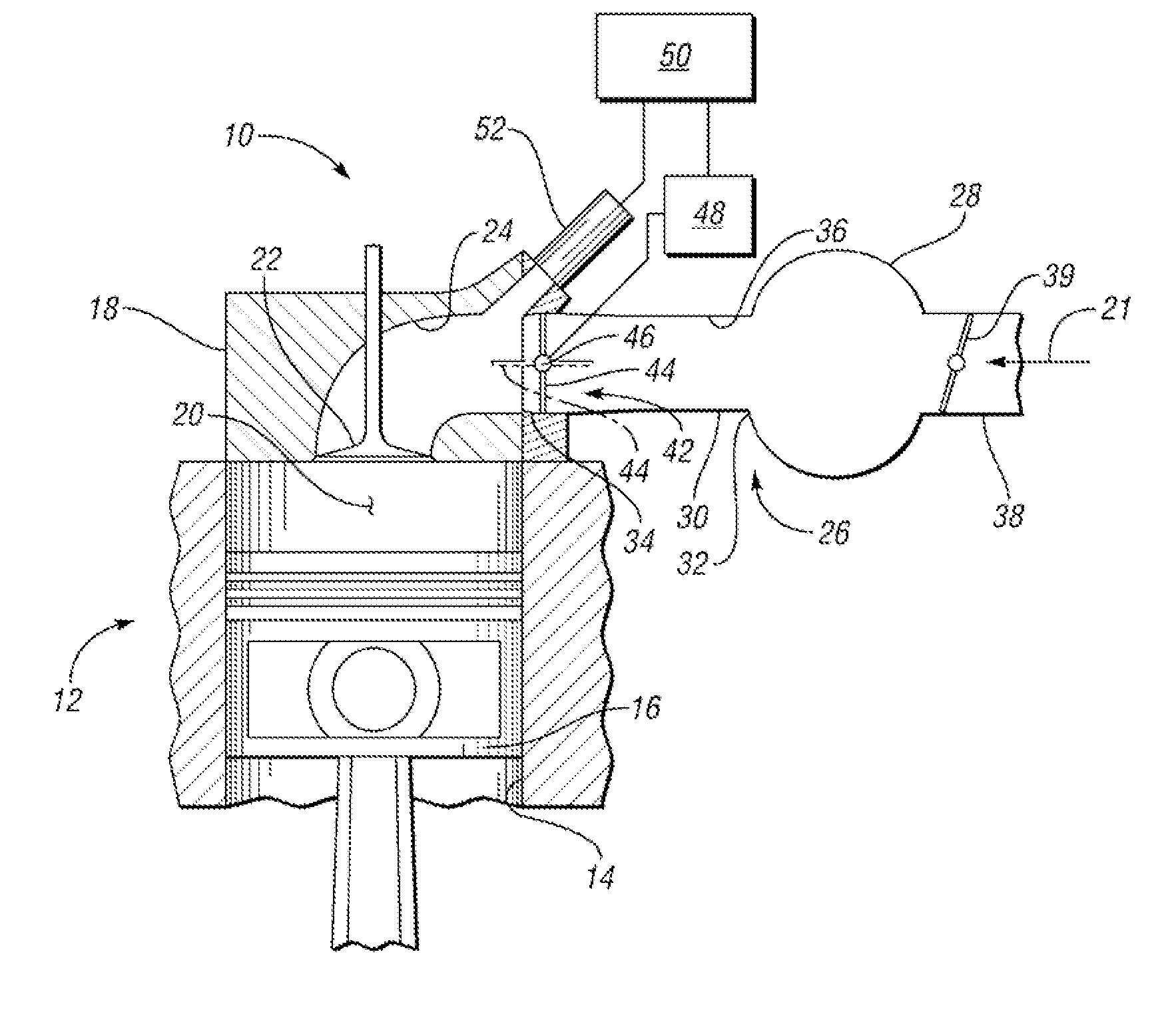
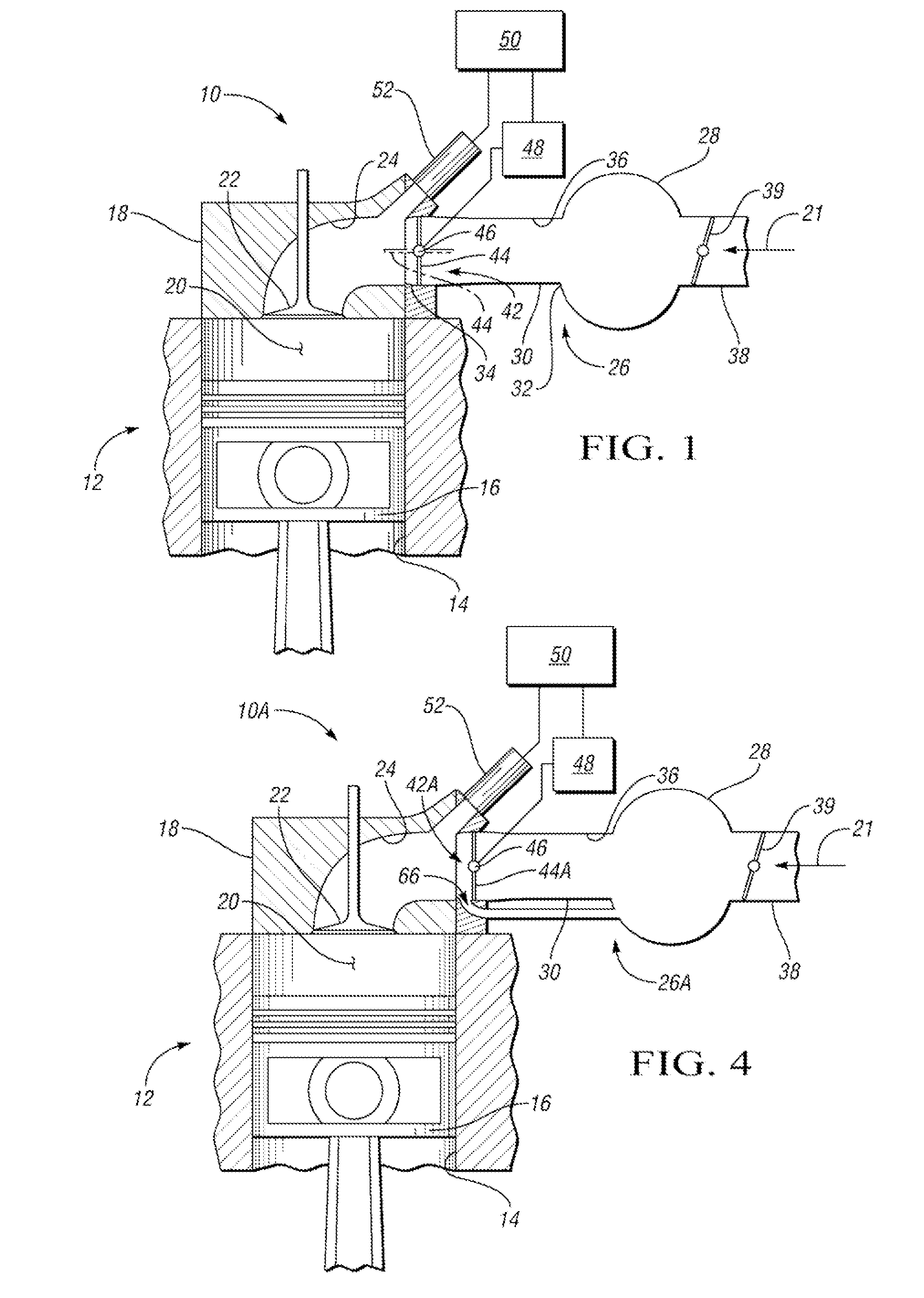
[0010]Referring to the drawings wherein like reference numbers correspond to like or similar components throughout the several figures, a portion of an internal combustion engine is schematically depicted and generally indicated as 10. The internal combustion engine 10 includes a cylinder block 12 defining a cylinder bore 14 having a piston 16 reciprocally movable therein. A cylinder head 18 is mounted to the cylinder block 12 and is operable to close one end of the cylinder bore 14. The cylinder bore 14, cylinder head 18, and piston 16 cooperate to form a variable volume combustion chamber 20 within which fuel and intake air, indicated by arrow 21, are combusted during operation of the internal combustion engine 10.

[0011]The cylinder head 18 contains a selectively openable poppet valve or intake valve 22. The intake valve 22 is operable to selectively open an intake port 24, defined by the cylinder head 18, to the combustion chamber 20. Therefore, the intake valve 22 is operable to...


PUM


Abstract

An intake manifold assembly is provided having a plenum and an intake runner in communication with the plenum. The intake runner has an outlet end. A selectively closeable throttle plate is disposed within the intake runner and is operable to selectively limit the flow of intake air through the intake runner. The throttle plate is selectively and variably movable between a fully opened position and a fully closed position. An orifice, defined by one of the intake runner and the throttle plate, has an opening area of approximately fifteen percent or less of a cross sectional area of the outlet end. An internal combustion engine incorporating the intake manifold assembly is also disclosed.

Description

TECHNICAL FIELD[0001]The present invention relates to an intake manifold assembly for an internal combustion engine.BACKGROUND OF THE INVENTION[0002]An internal combustion engine typically incorporates an intake manifold assembly to provide intake air to an intake port for subsequent introduction to a combustion chamber where it is combusted with an amount of fuel. The intake manifold assembly typically includes a plenum and at least one intake runner in communication with the plenum and intake port. Conventional intake manifold assemblies allow unrestricted communication between the intake runner and intake port, thereby allowing an amount of products of combustion, sometimes referred to as residual gas, to traverse the intake port and enter the intake runner and plenum during low speed and load modes of engine operation, such as idle or near idle. This condition is most prevalent with internal combustion engines having a large amount of valve overlap, i.e. the period between the o...

Claims


Application Information

Patent Timeline
Patent Type & Authority Applications(United States)
IPC IPC(8): F02M35/104
CPCF02B29/086F02B31/06Y02T10/146F02M35/10262F02M35/104F02M35/10032Y02T10/12
Inventor ZHANG, JIAN JUNWU, KO-JENBERRY, WILLIAM A.ELMSLIE, JAMES C.
Owner GM GLOBAL TECH OPERATIONS LLC
Why Eureka
Try Eureka