Liquid crystal display device including driving circuit and method of fabricating the same

a driving circuit and liquid crystal display technology, applied in the direction of optics, transistors, instruments, etc., can solve the problems of difficult implementation of driving circuits using hydrogenated amorphous silicon, unstable tft, and difficult to achieve the effects of reducing the number of mask processes, reducing the cost of fabrication, and improving production yield

Active Publication Date: 2008-06-19
LG DISPLAY CO LTD
View PDF0 Cites 18 Cited by
  • Summary
  • Abstract
  • Description
  • Claims
  • Application Information

AI Technical Summary

Benefits of technology

[0022]An object of the present invention is to provide a liquid crystal display device having a bottom gate structure and a method of fabricating the same through a reduced number of mask processes.
[0023]Another object of the present invention is to provide an array substrate for a liquid crystal display device and a method of fabricating the same where production yield is improved and fabrication cost is reduced based on a five-mask process.

Problems solved by technology

However, since the hydrogenated amorphous silicon has a disordered atomic arrangement, weak silicon-silicon (Si—Si) bonds and dangling bonds exist in the hydrogenated amorphous silicon.
As a result, this metastability makes the TFT unstable.
Electrical characteristics of the hydrogenated amorphous silicon are especially degraded due to light irradiation.
Furthermore, a TFT using the hydrogenated amorphous silicon is difficult to be implemented in a driving circuit due to degraded electric characteristics such as a low field effect mobility between about 0.1 cm2 / Vsec to about 1.0 cm2 / Vsec, and poor reliability.
The driving IC and its packaging increase the LCD device production cost.
Thus, bonding of the TCP and the a-Si TFT substrate becomes harder.
Since the related art mask process includes steps of coating PR, exposing PR, and developing PR, increase in production cost and fabrication time as well as a reduced production yield results from an increased number of masks.
In addition, reliability of a thin film transistor is reduced accordingly.

Method used


Image

  • Liquid crystal display device including driving circuit and method of fabricating the same
  • Liquid crystal display device including driving circuit and method of fabricating the same
  • Liquid crystal display device including driving circuit and method of fabricating the same

Examples


Embodiment Construction

[0039]Reference will now be made in detail to embodiments of the present invention, example of which is illustrated in the accompanying drawings. Wherever possible, similar reference numbers will be used throughout the drawings to refer to the same or like parts.

[0040]FIG. 4 is a schematic plane view showing an array substrate for a liquid crystal display device according to an exemplary embodiment of the present invention. FIG. 4 shows a display area and a pad area of the array substrate, and it does not show a driving area of the array substrate for simplicity.

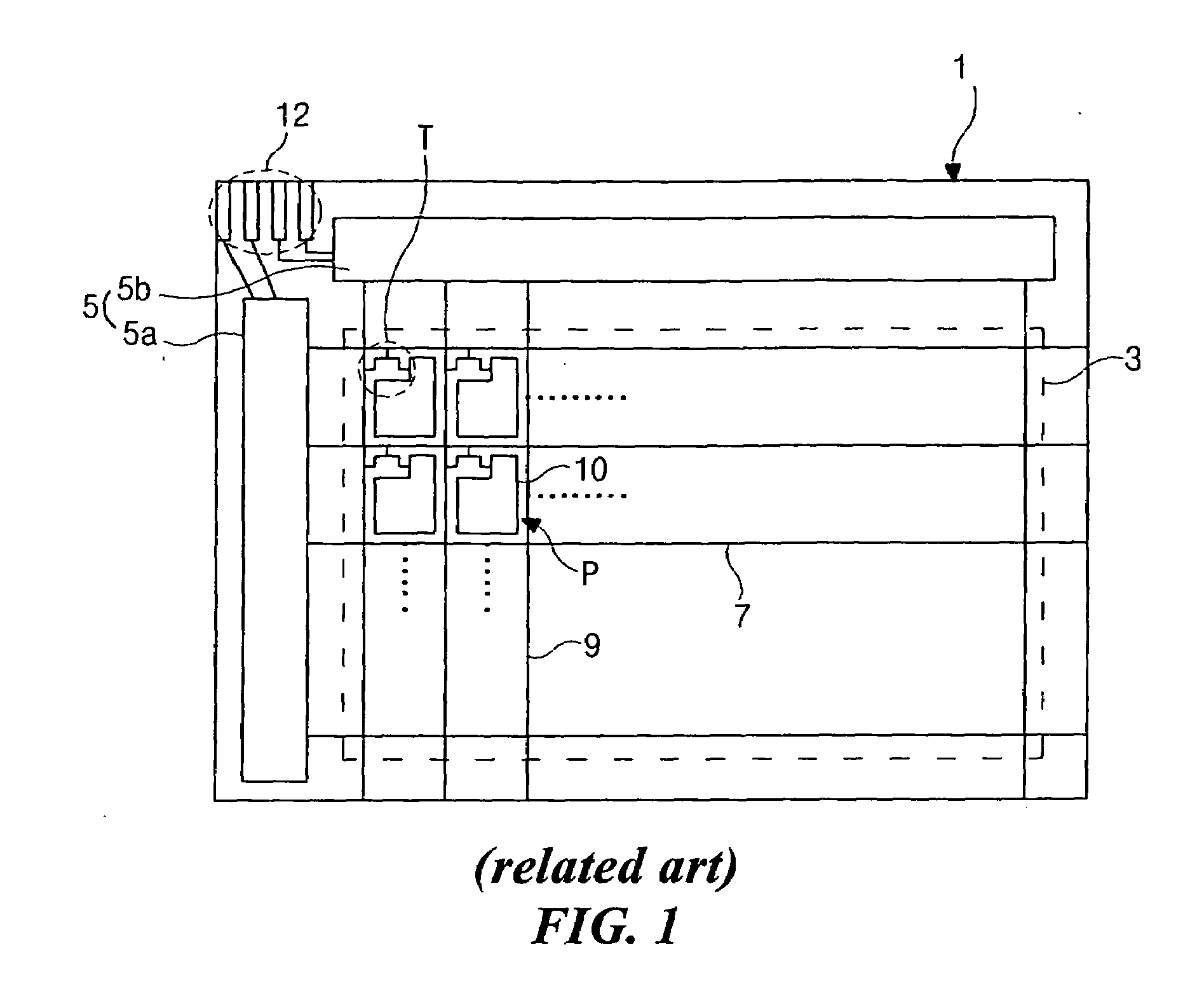
[0041]In FIG. 4, a gate line 112 and a data line 109 are formed on a substrate 101 in a display area “DPA.” A gate pad 170 is formed at one end of the gate line 112 and a data pad 175 is formed at one end of the data line 109. The gate line 112 intersects the data line 109 to define a pixel region “P”. A thin film transistor (TFT) “Tr” formed as a switching element is connected to the gate line 112 and the data line 109. The...


PUM

PropertyMeasurementUnit
wavelengthsaaaaaaaaaa

Abstract

A method of fabricating an array substrate structure for a liquid crystal display device includes defining a display area and a non-display area on a substrate, the display area having a pixel TFT portion and a pixel electrode area, and the non-display area having an n-type driving TFT portion and a p-type driving TFT portion; forming a first gate electrode in the display area, a second and a third gate electrodes and a first capacitor electrode in the non-display area; an amorphous silicon layer on the substrate; crystallizing the amorphous silicon layer to a polycrystalline silicon layer and doping specific portions of the polycrystalline silicon layer with plurality of impurity concentrations; and forming a first semiconductor layer in the display area, a second and a third semiconductor layers and a second capacitor electrode in the non-display area.

Description

[0001]This application claims the benefit of Korean Patent Application No. 2004-023445, filed in Korea on Apr. 6, 2004, which is hereby incorporated by reference.BACKGROUND OF THE INVENTION[0002]1. Field of the Invention[0003]The present invention relates to a liquid crystal display device, and more particularly, to a display device including a driving circuit polycrystalline silicon driving circuit and a method of fabricating the same.[0004]2. Discussion of the Related Art[0005]As the information age progresses, flat panel display (FPD) devices having high portability and low power consumption is becoming the trend of recent research and development. Among various types of FPD devices, liquid crystal display (LCD) devices are commonly used as monitors for notebook and desktop computers because of their ability to display high-resolution images, wide ranges of different colors, and moving images.[0006]In general, the LCD device includes a color filter substrate and an array substrat...

Claims


Application Information

Patent Timeline
Patent Type & Authority Applications(United States)
IPC IPC(8): H01L33/00G02F1/1362G02F1/136H01L21/77H01L21/84H01L27/12H01L27/13H01L29/786
CPCG02F1/13454H01L29/78621Y10S148/15H01L27/1288H01L27/1255G02F1/136
Inventor OH, KUM-MIHWANG, KWANG-SIK
Owner LG DISPLAY CO LTD
Why Eureka
Try Eureka