
Digital pulse-width control apparatus

Inactive Publication Date: 2008-06-19
IND TECH RES INST
View PDF2 Cites 14 Cited by
  • Summary
  • Abstract
  • Description
  • Claims
  • Application Information

AI Technical Summary

Benefits of technology

[0013]The present invention is directed to a digital pulse-width control apparatus, which uses an input module to vary a clock signal, so as to reduce the limitation of a duty cycle of the clock signal on the digital pulse-width control apparatus.
[0014]The present invention is also directed to a digital pulse-width control apparatus, which uses a pulse-width modulation module to generate an adjustable clock signal or an anti-phase signal of the adjustable clock signal, so as to reduce the number of programmable delay circuits.
[0023]The present invention uses the input module to reduce the limitation of the duty cycle of the clock signal on the digital pulse-width control apparatus. In another aspect, the circuit structure formed by the pulse-width modulation module, the digital delay locked loop, and a plurality of programmable delay circuit expands the range of the duty cycle of the output clock signal, and reduces the circuit layout area of the digital pulse-width control apparatus as well.

Problems solved by technology

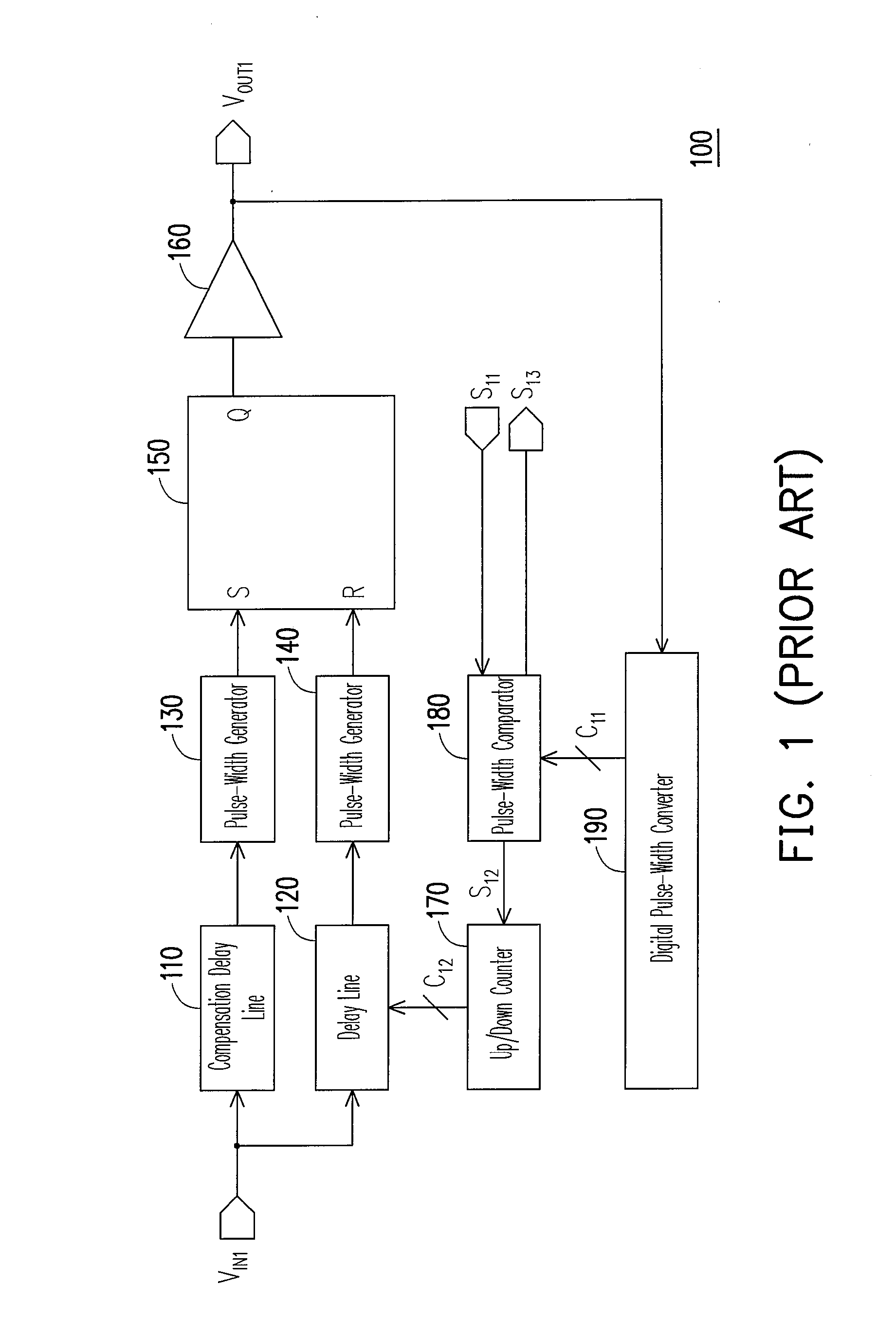
However, in actual applications, the range of the duty cycle of the input clock signal VIN1 is limited by the circuit characteristics of the compensation delay line 110 and the delay line 120.
As the digital pulse-width converter 190 cannot find a balance between the layout area and the resolution of detection, the range of the duty cycle of the output clock signal VOUT1 is greatly limited.
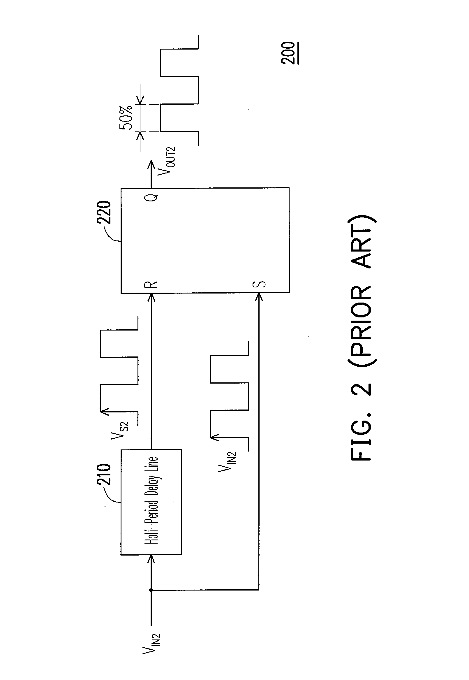
However, the conventional pulse-width control apparatus 200 has an inevitable defect, that is, the duty cycle of the output clock signal VOUT2 is fixed to be 50%.
However, in actual applications, the clock width modulator 310 cannot regulate the input clock signal VIN3 of different frequencies with a same detection resolution.

Method used


Image

  • Digital pulse-width control apparatus
  • Digital pulse-width control apparatus
  • Digital pulse-width control apparatus

Examples


Embodiment Construction

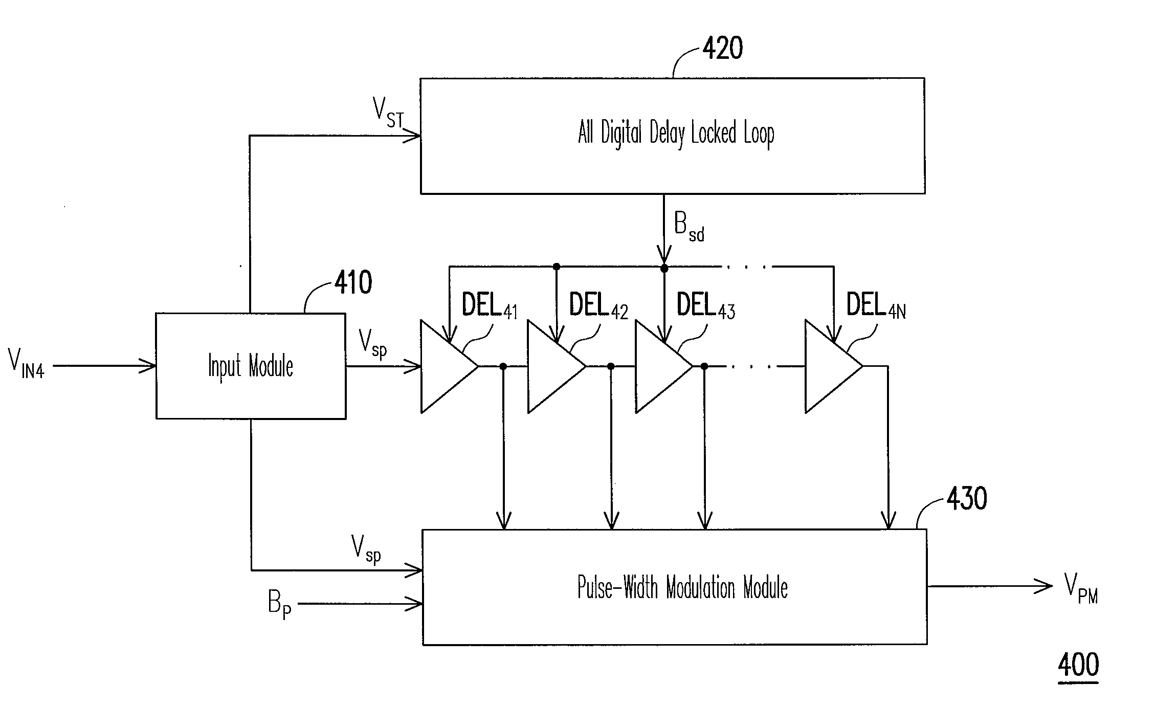
[0039]FIG. 4 is an architectural view of a digital pulse-width control apparatus according to an embodiment of the present invention. Referring to FIG. 4, the digital pulse-width control apparatus 400 includes an input module 410, a digital delay locked loop 420, programmable delay circuits DEL41-DEL4N and a pulse-width modulation module 430, wherein N is a positive integer. The digital delay locked loop 420 and the pulse-width modulation module 430 are coupled to the input module 410. The programmable delay circuits DEL41-DEL4N are connected in series, an input terminal of the programmable delay circuit DEL41 is coupled to the input module 410, and output terminals of the programmable delay circuits DEL41-DEL4N are coupled to the pulse-width modulation module 430.

[0040]In order to avoid the clock signal VIN4 disappearing in transmission when the pulse-width of the clock signal VIN4 is very narrow, the digital pulse-width control apparatus 400 uses the input module 410 to receive th...


PUM


Abstract

A digital pulse-width control apparatus including an input module, a digital delay locked loop, a plurality of programmable delay circuits connected in series, and a pulse-width modulation module is provided. The present invention uses the input module to vary a clock signal to reduce the limitation of a duty cycle of the clock signal to the digital pulse-width control apparatus.

Description

CROSS-REFERENCE TO RELATED APPLICATION[0001]This application claims the priority benefit of Taiwan application serial no. 95147030, filed Dec. 15, 2006. All disclosure of the Taiwan application is incorporated herein by reference.BACKGROUND OF THE INVENTION[0002]1. Field of the Invention[0003]The present invention relates to a digital pulse-width control apparatus. More particularly, the present invention relates to a digital pulse-width control apparatus free from an influence of a duty cycle of a clock signal.[0004]2. Description of Related Art[0005]For high-speed very large scale integrated (VLSI) circuits, in order to ensure the accuracy of duty cycle of a clock, a pulse-width control apparatus is developed. According to the circuit designs, pulse-width control apparatuses are classified into digital and analog types. The digital pulse-width control apparatuses have fine resistance to noises, and have the advantages of fast locking and stable systems, so they are currently widel...

Claims


Application Information

Patent Timeline
IPC IPC(8): H03L7/06
CPCH03K5/1565H03K5/133H03L7/0814
Inventor HUANG, HONG-YIJAN, SHIUN-DIANCHU, YUAN-HUA
Owner IND TECH RES INST
Learn More