Lightpipe for illuminating keys of a keyboard

a keyboard and light pipe technology, applied in the field of light pipes, can solve problems such as deterioration of the light carrying properties of plates, and achieve the effect of reducing power consumption

Inactive Publication Date: 2008-06-19
SHIPMAN MICHAEL
View PDF50 Cites 44 Cited by
  • Summary
  • Abstract
  • Description
  • Claims
  • Application Information

AI Technical Summary

Benefits of technology

[0030]In an additional preferred embodiment of the present invention, the light source is constructed of a substantially planar plate underlying the light channeling membrane of the keyboard. An alternative construction for the illuminating sheet of the light source is described in U.S. Pat. No. 5,045,755 issued to Appelberg and assigned to E-Lite Technologies, Inc. which is incorporated herein by reference. The illuminating sheet is a split electrode or parallel plate lamp consisting of a main body sandwiched between first and second conductive layers. Application of an alternating current to the planar sheet provides a luminescent sheet which can be adhesively attached to the bottom of the keyboard light channeling membrane. Moreover, the illuminating sheet is sufficiently thin as to not require significant modification to existing computer keyboard designs.
[0031]An additional preferred construction of the luminescent sheet can be obtained from MKS, Inc. located in Bridgeton, N.J., USA under the trademark designation Quantaflex™. The Quantaflex™ material is an electroluminescent lamp including luminescent phosphors embedded in the dielectric medium of a capacitor constructed in the form of a sheet. Electrodes, including at least one translucent electrode, form the top and bottom layers of the Quantaflex™ material. Upon application of an alternating current to the electrodes, the phosphors give off photons producing light in the visible spectrum. An advantage of the Quantaflex™ material is that the phosphors can be selectively encapsulated between the electrode layers of the luminescent sheet so as to selectively produce patterns of light emitted from the luminescent sheet. For example, for application with the present invention, it is preferred that the Quantaflex™ material be constructed to produce light only below and / or immediately adjacent to the key members so as to reduce power consumption.

Problems solved by technology

Preferably, but not necessarily, the plate is continuous and has no holes, or very few holes, which can significantly deteriorate the plate's light carrying properties.

Method used


Image

  • Lightpipe for illuminating keys of a keyboard
  • Lightpipe for illuminating keys of a keyboard
  • Lightpipe for illuminating keys of a keyboard

Examples


Embodiment Construction

[0072]While the present invention is susceptible of embodiment in various forms, as shown in the drawings, hereinafter will be described the presently preferred embodiments of the invention with the understanding that the present disclosure is to be considered as an exemplification of the invention, and is not intended to limit the invention to specific embodiments illustrated.

[0073]With reference to FIGS. 18-24, the light guide 49, also referred to herein as a luminescent planar sheet, includes a translucent plate 71 constructed in any number of shapes and sizes, but which is preferably constructed to have an elongate rectangular cross-section so as to have a top 73, bottom 75 and four sides 77. The translucent plate may be made of any of the numerous light-transmitting materials, but which is preferably made of an acrylic or polycarbonate material for cost and weight reasons. The plate further includes one or more cavity 79 which are recesses which project upwardly from the transl...


PUM


Abstract

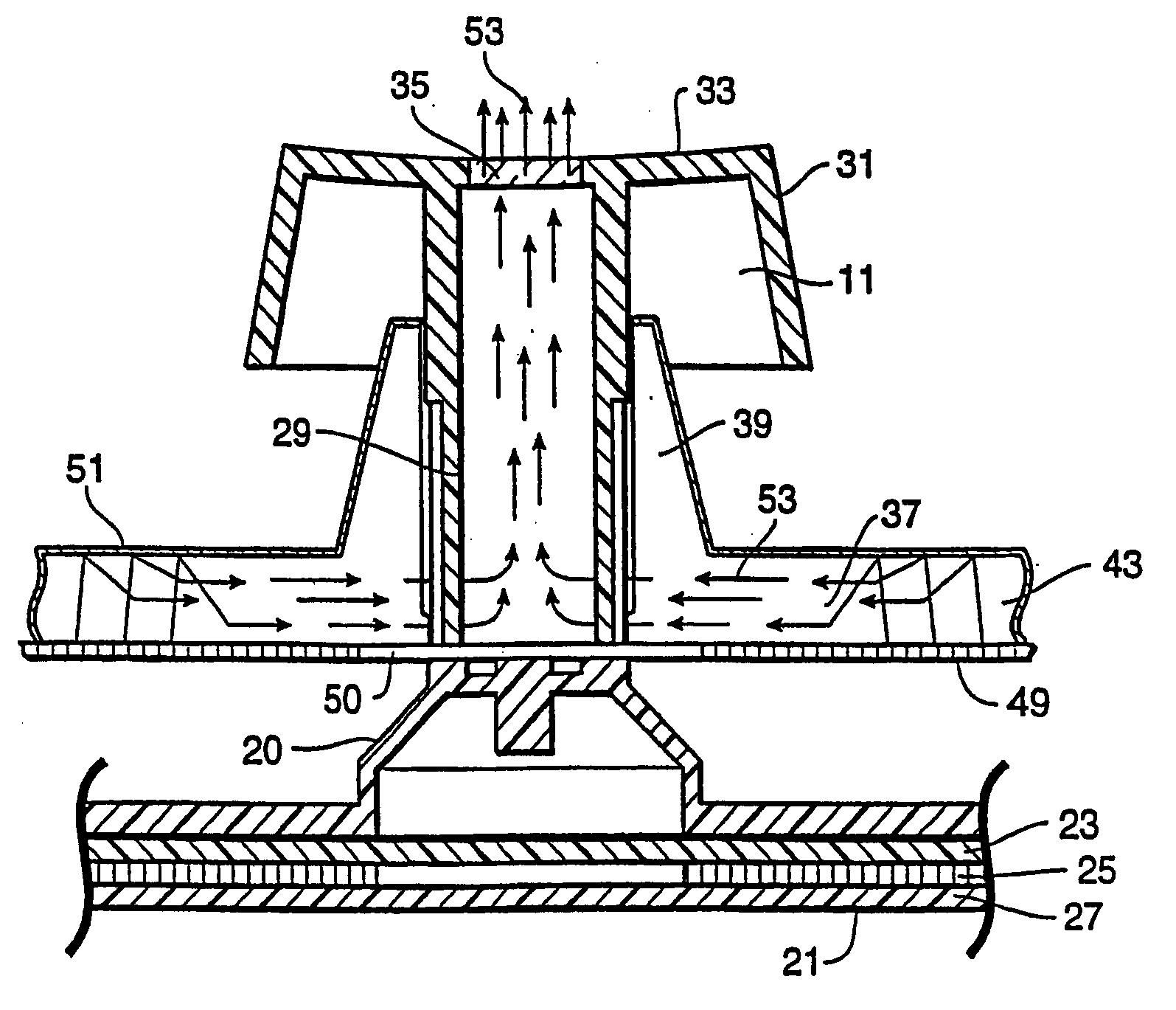
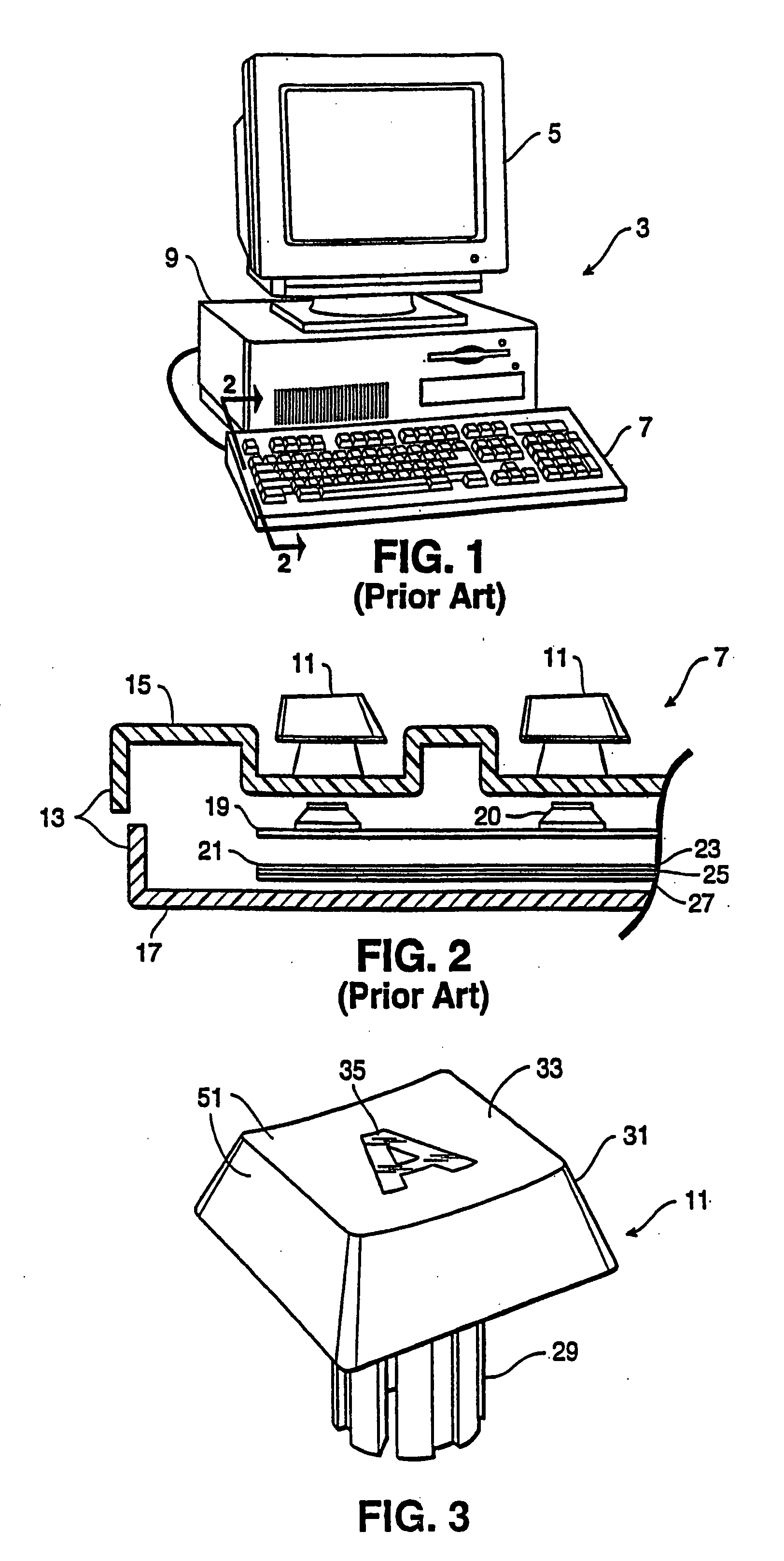
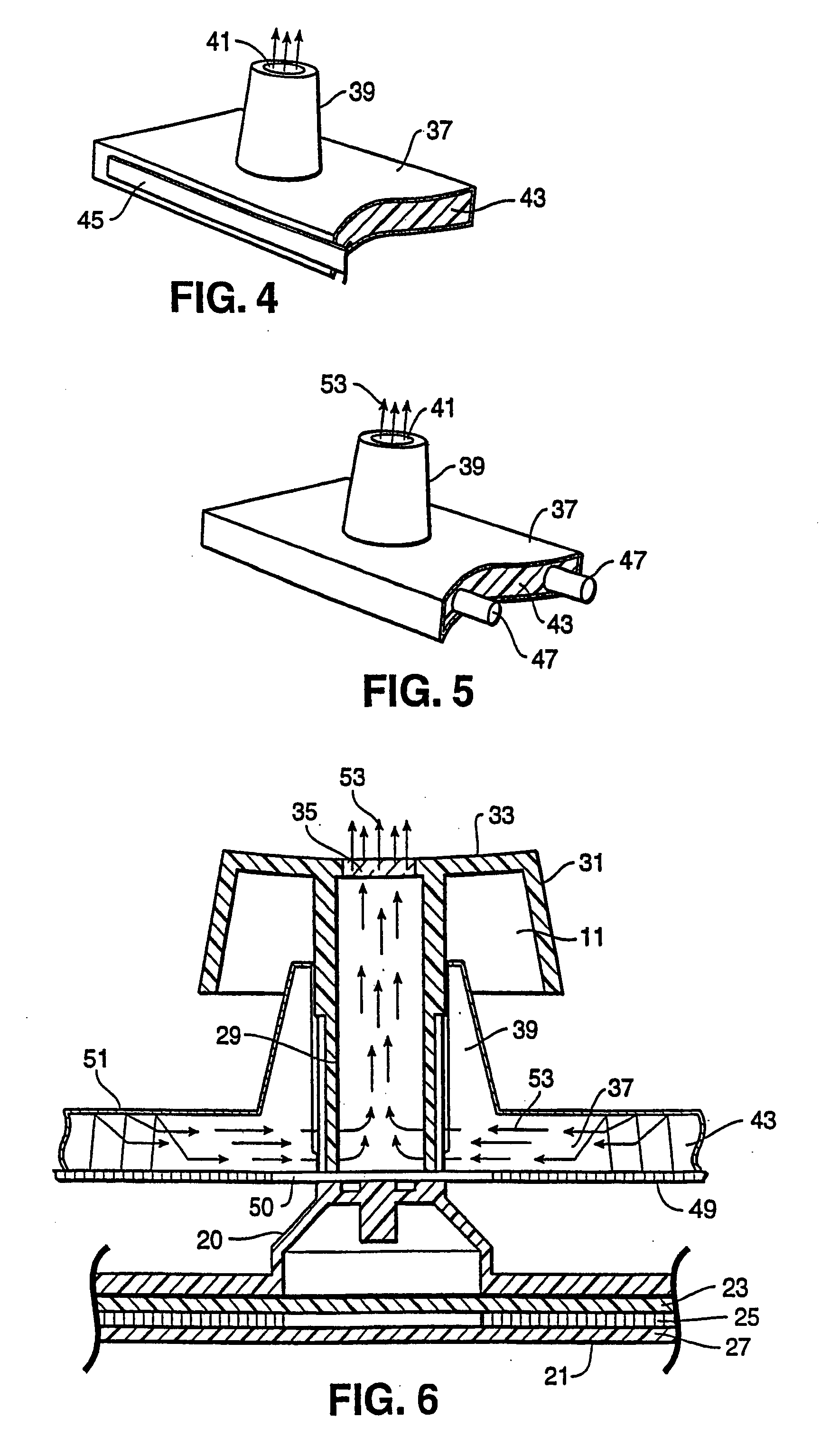
A light guide is provided for illuminating innumerable constructions, but which is ideally suited for illuminating the keys of a keyboard. The light guide includes a translucent planar plate having a top, a bottom and sides. Further, the light guide includes one or more cavities which project upwardly into the translucent plate from its bottom surface. The cavities are hollow or filled with a translucent material so that the translucent plate and the one or more cavities form translucent interfaces where the cavities interface with the plate. The light guide also includes a reflector which covers the plate bottom and cavity openings. Light produced by a light source, preferably in the form of one or more LEDs, is transmitted to and through the translucent plate until striking the plate-cavity interfaces where the light is refracted into the cavities' interior or reflected upwardly to the plate's upper surface. After initial refraction into a cavity, the light reflects off the reflector and travels again into the translucent plate until transmitted from the plate's upper surface. Preferably, light guide is positioned within a keyboard housing with the cavities underlying the keys so that light is transmitted from the translucent sheet to the keys.

Description

RELATED APPLICATIONS[0001]This application is a continuation-in-part application of U.S. patent application Ser. No. 11 / 038,308 filed Jan. 18, 2005, which in turn is a continuation-in-part application of U.S. patent application Ser. No. 10 / 294,396 filed on Nov. 14, 2002, now U.S. Pat. No. 6,918,677 issued Jul. 19, 2005, which in turn is a continuation-in-part application of U.S. patent application Ser. No. 09 / 899,960 filed on Jul. 6, 2001, now abandoned, which in turn is a continuation-in-part application of U.S. patent application Ser. No. 09 / 836,628 filed on Apr. 16, 2001, now U.S. Pat. No. 6,467,924 issued Oct. 22, 2002, which in turn is a continuation-in-part application of U.S. patent application Ser. No. 09 / 500,735, filed on Feb. 9, 2000, now U.S. Pat. No. 6,217,183 issued Apr. 17, 2001, which in turn is a continuation application of U.S. patent application Ser. No. 09 / 396,141, filed on Sep. 15, 1999, now abandoned.BACKGROUND OF THE INVENTION[0002]The present invention relates...

Claims


Application Information

Patent Timeline
Patent Type & Authority Applications(United States)
IPC IPC(8): H03M11/00
CPCG06F3/0202G06F3/0238
Inventor SHIPMAN, MICHAEL
Owner SHIPMAN MICHAEL
Why Eureka
Try Eureka