Rotary Encoder

a rotary encoder and encoder technology, applied in the direction of dynamo-electric machines, measurement apparatus bearings/suspensions, measurement apparatus housings, etc., can solve the problems of unwanted mechanical stress or load of the rotary encoder, rotation irregularities or torque fluctuations, affecting the exact measurement of the rotational speed and the rotational position,

Inactive Publication Date: 2008-06-19
DR JOHANNES HEIDENHAIN GMBH
View PDF7 Cites 5 Cited by
  • Summary
  • Abstract
  • Description
  • Claims
  • Application Information

AI Technical Summary

Benefits of technology

[0009]Example embodiments of the present invention provide a rotary encoder having a construction such that the influence due to stress deformations because of the different coefficients of thermal expa...

Problems solved by technology

The following problems exist in connection with conventional rotary encoders constructed in this manner.
Therefore, if there is a change of temperature in the rotary-transducer surroundings, an unwanted mechanical stress or load of the rotary encoder results because of the different coefficients of thermal expansion owing to the different properties of the two materials.
Due to the stress on the part of rotary-transducer base member 1, bearings 2 can deform, which may result in rotational irregularities or torque fluctuations of shaft 3.
Therefore, the danger exists of disadvantageously influencing the exact measurement of the rotational speed and the rotational position, i.e., disadvantageously influencing the positioning accuracy.
If the connection to the object to be measured is accomplished via a belt or something...

Method used


Image

  • Rotary Encoder
  • Rotary Encoder
  • Rotary Encoder

Examples


Embodiment Construction

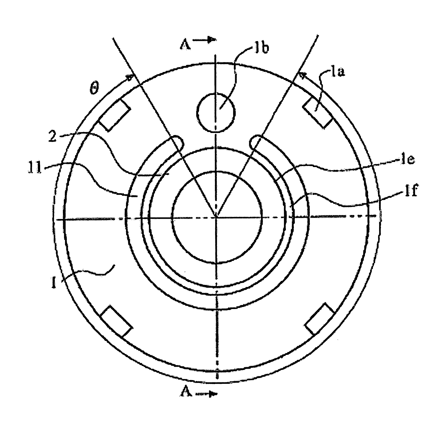
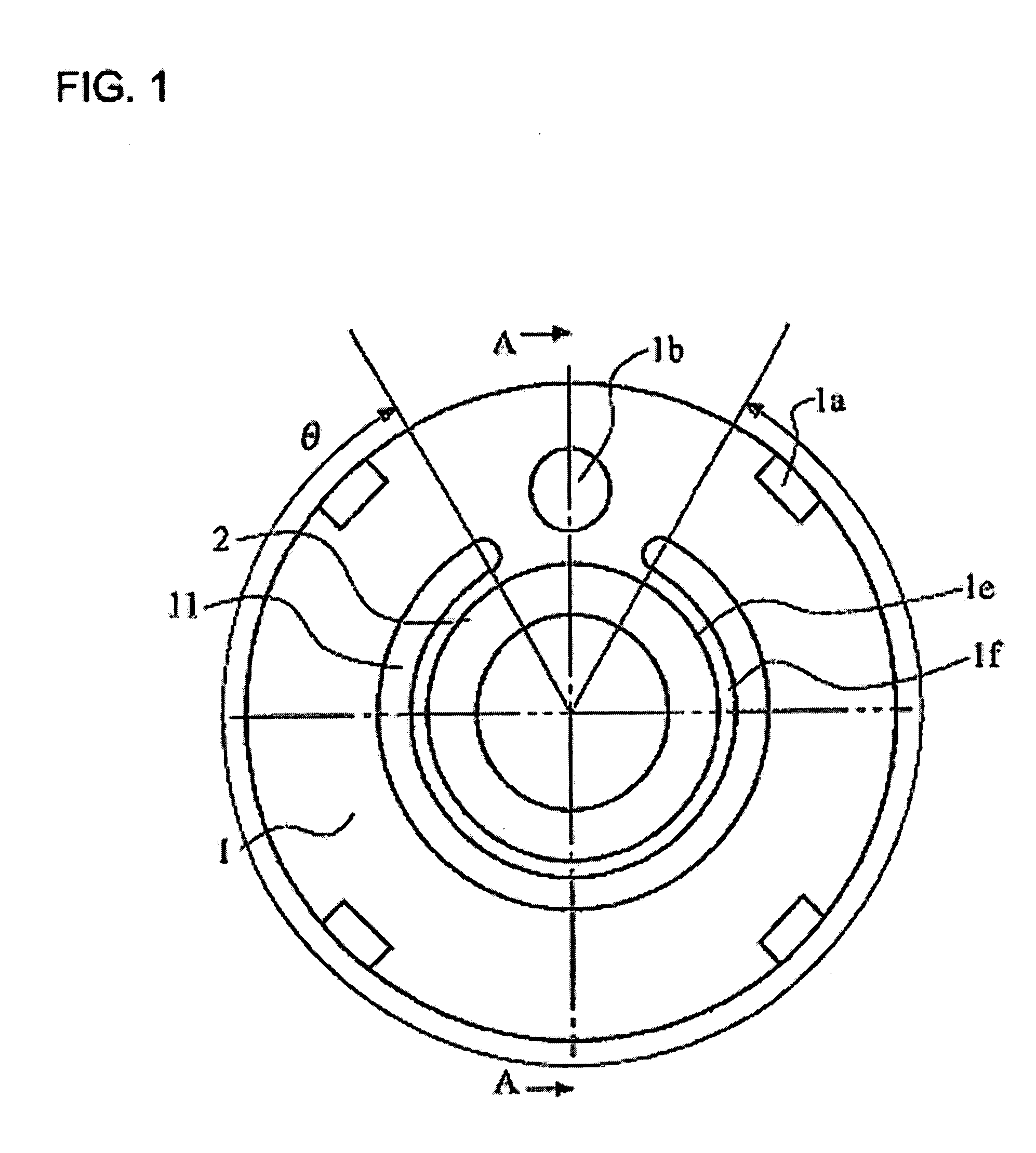
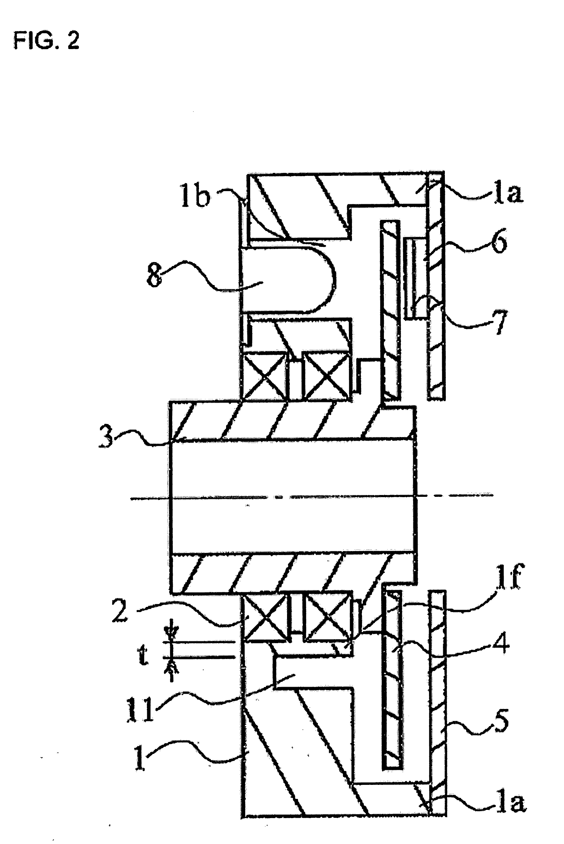
[0033]FIGS. 1 and 2 illustrate a rotary encoder according to an example embodiment of the present invention. FIG. 1 is a front view of the configuration of the rotary-transducer base member and the bearing area. FIG. 2 is a cross-sectional view taken along line A-A of FIG. 1, the view of FIG. 1 having been supplemented with further components of the rotary encoder. To make it easier to understand the arrangement, base-plate supports 1a, which are not actually located at this position in the cross-sectional view, are indicated in the view of FIG. 2.

[0034]According to the Figures, the rotary encoder includes a rotary-transducer base member 1, bearings 2 mounted at a bearing fixation region 1e of rotary-transducer base member 1, and a shaft 3 in the form of a hollow shaft which is mounted on bearings 2 and thereby retained in a manner allowing rotation. Two bearings 2 are used in this example. Shaft 3 is retained at two points by the two bearings disposed at a slight distance from each...


PUM


Abstract

A rotary encoder for determining the rotation of an object to be measured includes a shaft that is coupled to the rotation of the object to be measured, as well as at least one bearing in which the shaft is rotationally mounted. The rotary encoder also has a rotary-transducer base member having a bearing fixation region at which the bearing is fixed in position, at least one depression area being formed continuously with a defined depth on the rotary-transducer base member along the periphery of the bearing fixation region such that it surrounds at least half the periphery of the bearing fixation region.

Description

FIELD OF THE INVENTION[0001]The present invention relates to a rotary encoder, which, for example, is disposed on the shaft of a rotor in a motor and determines the number of revolutions per unit time and / or the rotational-angle position of the rotor.BACKGROUND INFORMATION[0002]Conventional rotary encoders are constructed as shown, for example, in FIGS. 8 and 9. FIG. 8 is a front view with the configuration of the rotary-transducer base member and the bearing area, and FIG. 9 is a cross-sectional view taken along line A-A of FIG. 8, the view of FIG. 8 having been supplemented with further components of the rotary encoder. To make it easier to understand the arrangement, base-plate supports 1a, which are not actually located at this position in the cross-sectional view, are also indicated in FIG. 9.[0003]The rotary encoder has a rotary-transducer base member 1, bearings 2 disposed on rotary-transducer base member 1, and a hollow shaft 3 rotatably supported by these bearings 2. The sh...

Claims


Application Information

Patent Timeline
IPC IPC(8): G01B11/26G01D5/26
CPCG01D5/34738G01D11/245G01D11/02G01D11/24
Inventor NAKAMURA, YOSHIYUKITAKAHASHI
Owner DR JOHANNES HEIDENHAIN GMBH
Why Eureka
Try Eureka