Driving circuit and related driving method for providing feedback control and open-circuit protection

a driving circuit and feedback control technology, applied in the direction of electric variable regulation, process and machine control, instruments, etc., can solve the problems of many other electrical components, easy damage or destruction, and the forward bias voltage of each light emitting diode b>240/b> is not identical

Active Publication Date: 2008-06-19
IML HONG KONG LTD
View PDF4 Cites 43 Cited by
  • Summary
  • Abstract
  • Description
  • Claims
  • Application Information

AI Technical Summary

Benefits of technology

[0016]It is an objective of the claimed disclosure to provide a driving method for providing feedback control and open-circuit protection.
[0017]According to an embodiment of the present disclosure, a driving method for providing feedback control and open-circuit protection is disclosed. The driving method includes providing a first constant current to a first light-emitting device, providing a driving voltage to an input end of the first light-emitting device, generating a first switch control signal to control turning on and off a first switch, connecting the first switch between an output end of the first light-emitting device and a feedback signal, generating the feedback signal according to the first switch control signal, and adjusting the driving voltage according to the feedback signal.
[0018]In one embodiment, the driving method further includes providing a second constant current to a second light-emitting device, pro

Problems solved by technology

LEDs are semiconductor devices that convert electrical energy directly into light, and, like many other electrical components, are susceptible to damage or destruction when exposed to excessive currents or voltages.
However, due to limitations of the materials and the manufa

Method used


Image

  • Driving circuit and related driving method for providing feedback control and open-circuit protection
  • Driving circuit and related driving method for providing feedback control and open-circuit protection
  • Driving circuit and related driving method for providing feedback control and open-circuit protection

Examples


Embodiment Construction

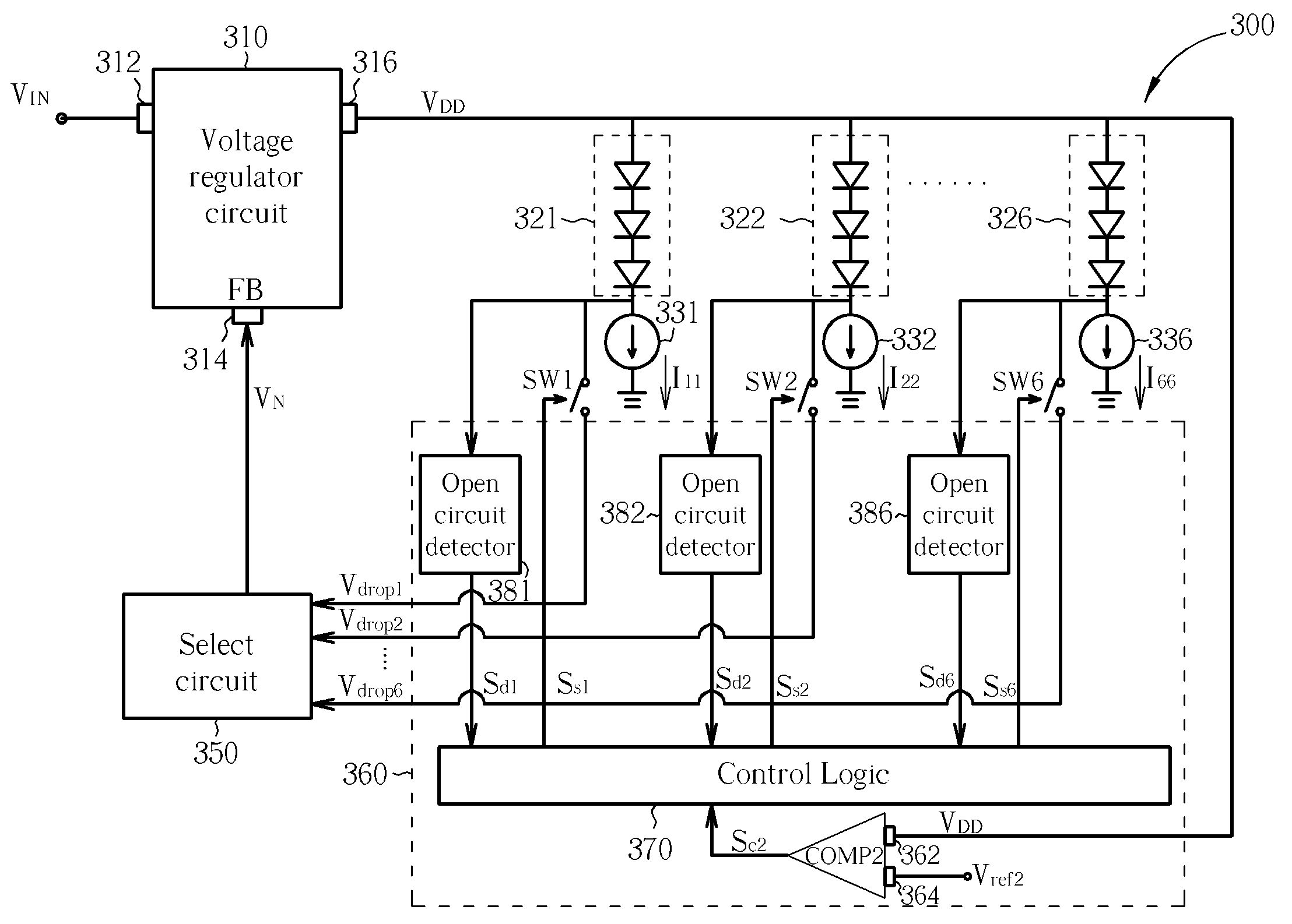
[0029]Please refer to FIG. 3. FIG. 3 is a diagram of a driving circuit 300 for providing feedback control and open-circuit protection according to a first embodiment of the present invention. The driving circuit 300 includes a voltage regulator circuit 310, six light-emitting devices 321-326, six constant-current suppliers 331-336, a select circuit 350, an analysis and decision circuit 360, and six switches SW1-SW6. The voltage regulator circuit 310 has a first input end 312 for receiving an input voltage VIN, a second input end 314 for receiving a feedback signal FB, and an output end 316 that is coupled to the six light-emitting devices 321-326. The voltage regulator circuit 310 is used for providing a driving voltage VDD to all six light-emitting devices 321-326. The six constant-current suppliers 331-336 are individually used for providing a constant current for driving the corresponding light-emitting device. For example, the first constant-current supplier 331 provides a first...


PUM


Abstract

A driving circuit includes a first light-emitting device, a first constant-current supplier, a voltage regulator circuit, an analysis and decision circuit, and a first switch. The first constant-current supplier provides a constant current to the first light-emitting device. The voltage regulator circuit provides a driving voltage to the first light-emitting device and adjusts driving voltage according to a feedback signal. The analysis and decision circuit is coupled to the voltage regulator circuit and the first light-emitting device. The analysis and decision circuit generates a first switch control signal. The first switch is coupled to the first light-emitting device, the analysis and decision circuit, and the voltage regulator circuit. The first switch is turned on and off according to the first switch control signal.

Description

CROSS REFERENCE TO RELATED APPLICATIONS[0001]This application claims the benefit of U.S. Provisional Application No. 60 / 870,410, filed Dec. 18, 2006, and included herein by reference.BACKGROUND OF THE INVENTION[0002]1. Field of the Invention[0003]The invention relates to a driving circuit and related method for providing feedback control and open-circuit protection, and more particularly, to a driving circuit and related method utilizing an analysis and decision circuit to detect status of light-emitting devices for providing feedback control and open-circuit protection.[0004]2. Description of the Prior Art[0005]Currently, light emitting diodes (LEDs) are developed and applied to backlight modules for replacing conventional CCFLs since LEDs have advantages of small size and low power consumption. Light emitting diodes have found a myriad of applications in many electrical circuits produced for consumer, commercial, industrial, and military uses. LEDs are semiconductor devices that c...

Claims


Application Information

Patent Timeline
IPC IPC(8): H02H7/00
CPCH05B33/0815Y02B20/341H05B33/0827H05B33/0818H05B45/397H05B45/46Y02B20/30
Inventor CHIANG, YUNG-HSINWANG, SHIH-YUAN
Owner IML HONG KONG LTD
Why Eureka
Try Eureka