

Optical transmission component and production method thereof
a technology of optical transmission and production method, applied in the field of optical transmission components, can solve the problems of increasing the number of components, reducing and increasing the cost of assembling or alignment, so as to reduce the work of assembling the optical transmission component and reduce the production cost. , the effect of reducing the number of components
- Summary
- Abstract
- Description
- Claims
- Application Information
AI Technical Summary
Benefits of technology
Problems solved by technology
Method used
Image

Examples
first embodiment
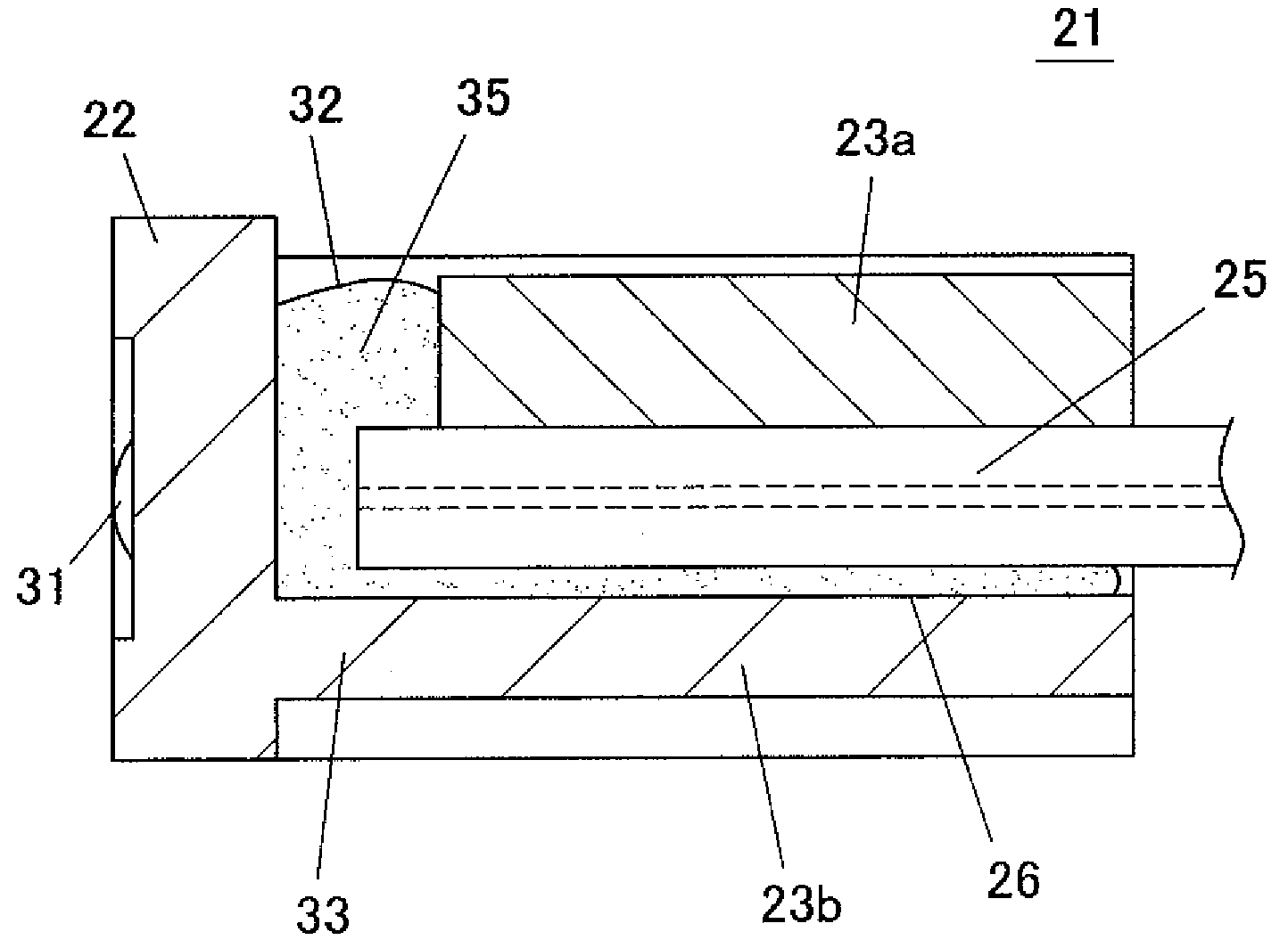
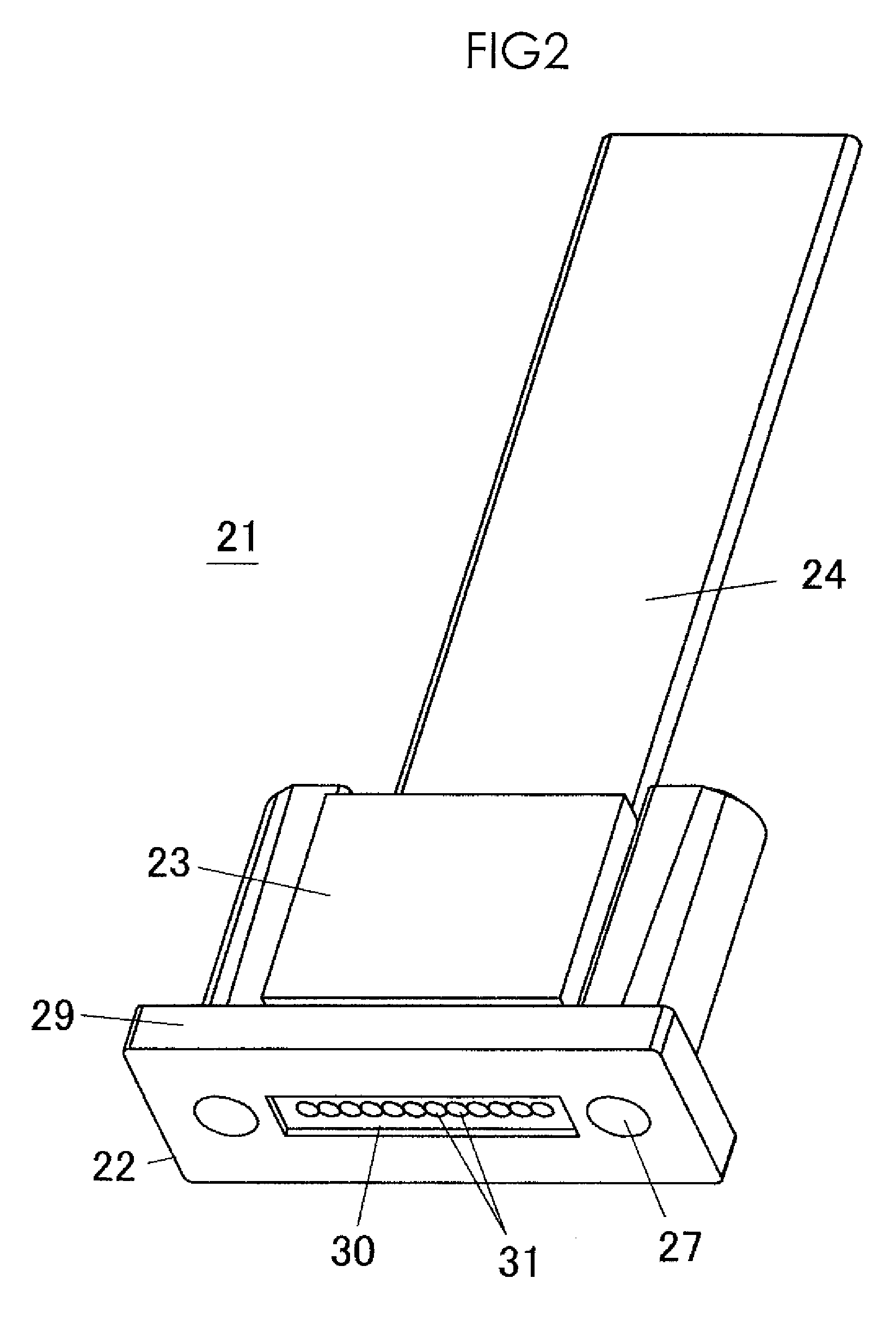
[0056]FIG. 2 shows a perspective view of an appearance of an optical transmission component 21 according to a first embodiment of the present invention, and FIG. 3 shows an exploded perspective view of the optical transmission component 21. FIG. 4 shows a rear view of the optical transmission component 21, FIG. 5 shows a sectional view taken along a lengthwise direction of the optical transmission component 21, and FIG. 6 shows a sectional view of a state in which the bonding agent is removed from the sectional view of FIG. 5 in the optical transmission component 21.
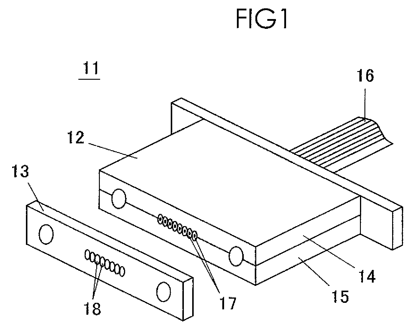
[0057]The optical transmission component 21 includes an optical function array 22 (optical function portion), a fiber holder 23 (optical transmission line holder), and a fiber array 24. The fiber array 24 is a tape core including a plurality of fiber cores 25 which are of the optical transmission line. In the fiber array 24, the whole of the fiber cores 25 arranged in parallel at constant pitches are coated with an armor...
second embodiment
[0085]FIG. 13 schematically shows a sectional view of a configuration of an optical transmission component 41 according to a second embodiment of the present invention. The optical transmission component 41 has the substantially same structure as the optical transmission component 21 of the first embodiment, so that only the different structure will be described (the same holds true for the following embodiments).
[0086]In the space 32 of the optical transmission component 41, an inclined surface 42 is formed over the whole width from a lower portion of the backside of the optical function array 22 to the upper surface of the connection portion 33. The fiber cores 25 are placed in the V-shape grooves 26, and the fiber cores 25 are pushed to cause the lower portions of the end faces of the fiber cores 25 to abut on the inclined surface 42, whereby a distance y between the backside of the optical function array 22 and the end faces of the fiber cores 25 can be kept evenly.
[0087]The res...
third embodiment
[0088]FIG. 14 schematically shows a sectional view of a configuration of an optical transmission component 51 according to a third embodiment of the present invention. In the space 32 of the optical transmission component 51, a projection 52 is projected from a lower end portion in the backside of the optical function array 22. The projection 52 is formed over the whole width of the space 32. The fiber cores 25 are placed in the V-shape grooves 26, and the fiber cores 25 are pushed to cause the lower portions of the end faces of the fiber cores 25 to abut on the projection 52, whereby a distance δ between the backside of the optical function array 22 and the end faces of the fiber cores 25 can be kept evenly. Desirably the projection 52 is provided below a center portion of the fiber core 25 such that the center portion of the fiber core 25 is not caught by the projection 52.
PUM
 Abstract
Description
Claims
Application Information