High density fiber optic hardware

Inactive Publication Date: 2008-06-19
CORNING OPTICAL COMM LLC
View PDF99 Cites 92 Cited by
  • Summary
  • Abstract
  • Description
  • Claims
  • Application Information

AI Technical Summary

Benefits of technology

[0008]The various embodiments of the present invention address the above needs and achieve other advantages by providing various fiber optic hardware and hardware components that include improved size, functionality, density, and other features. The

Problems solved by technology

In other words, it is oftentimes the case that the physical and performance limitations of the optical fibers partly define assembly structure a

Method used


Image

  • High density fiber optic hardware
  • High density fiber optic hardware
  • High density fiber optic hardware

Examples


Embodiment Construction

[0035]The present invention now will be described more fully hereinafter with reference to the accompanying drawings, in which some, but not all embodiments of the invention are shown. Indeed, the invention may be embodied in many different forms and should not be construed as limited to the embodiments set forth herein; rather, these embodiments are provided so that this disclosure will satisfy applicable legal requirements. Although apparatus and methods for providing high density fiber optic hardware are described and shown in the accompanying drawings with regard to specific types of fiber optic hardware components, it is envisioned that the functionality of the various apparatus and methods may be applied to any now known or hereafter devised fiber optic hardware in which it is desired to provide a high density of fiber optic connections or other fiber management. Like numbers refer to like elements throughout.

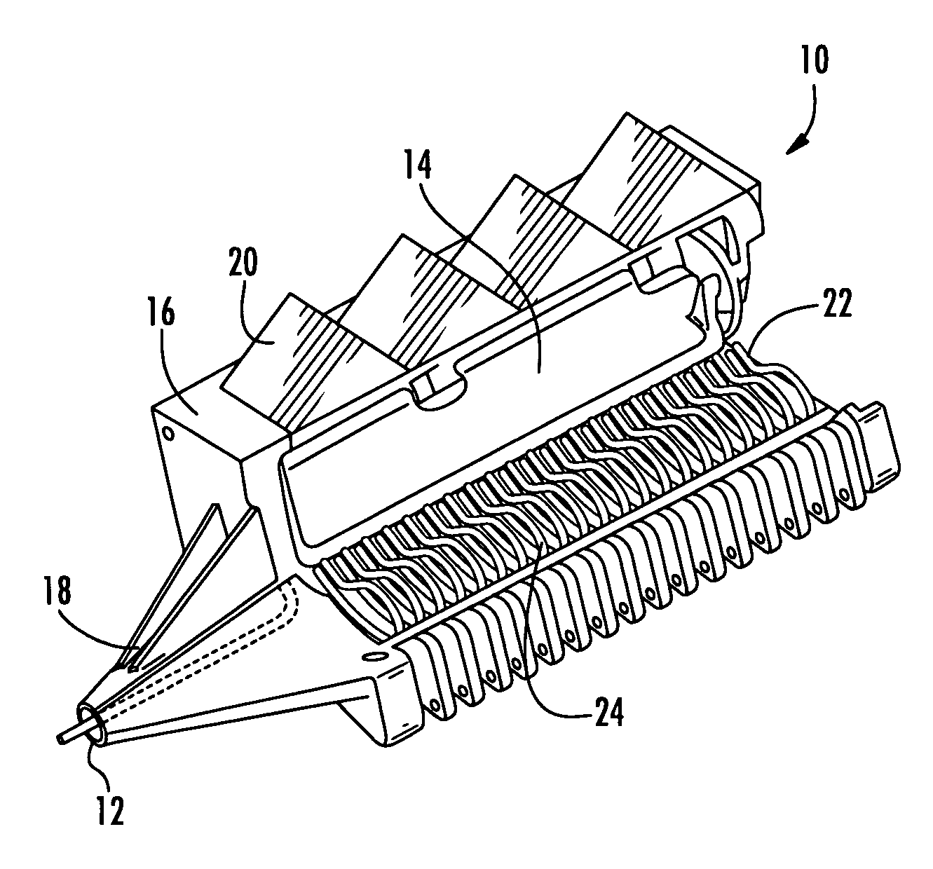
[0036]With reference to FIGS. 3-20, various fiber optic hardware com...


PUM


Abstract

There is provided fiber optic hardware and hardware components adapted to provide a desired amount of fiber optic connectivity and/or functionality for a desired amount of volume, materials, etc. The fiber optic hardware components include, but are not limited to multiports, local convergence points (LCPs), particularly LCPs for multiple dwelling units or similar applications, network interface devices, equipment frames, and fiber distribution hubs. Certain fiber optic hardware components are adapted to accommodate microstructured optical fiber or other bend performance optical fiber.

Description

CROSS-REFERENCE TO RELATED APPLICATIONS[0001]This application incorporates by reference U.S. patent application entitled “FIBER OPTIC CABLES AND ASSEMBLIES AND THE PERFORMANCE THEREOF”, filed this same day and assigned to Corning Cable Systems LLC.BACKGROUND OF THE INVENTION[0002]1. Field of the Invention[0003]The present invention is related to fiber optic hardware components, and more particularly, to novel fiber optic hardware and hardware components.[0004]2. Description of Related Art[0005]Along with the increase in the deployment of “Fiber-to-the-Premises” (FTTP) optical networks, a need has arisen for increasing the performance, manageability, handleability, and flexibility of fiber optic cables, cable assemblies, and network components in general. With respect to outdoor installation environments, cables, cable assemblies, and other network components are being developed that are more easily interconnected and installed within their environment, such as within aerial installa...

Claims


Application Information

Patent Timeline
IPC IPC(8): G02B6/00
CPCG02B6/02357G02B6/02366G02B6/4472G02B6/4441G02B6/14
Inventor ESCOTO, ALEJANDRO RAIGOZASANCHEZ, MANUEL ALEJANDRO LOPEZSALINAS, OCTAVIO BELTRANPAVON, GERARDOLUTHER, JAMES P.LEWALLEN, CHRISTOPHER PAULHURLEY, WILLIAMMITCHELL, TODD EDWARDGARCIA, CESAR GERONIMOGIRAUD, WILLIAM
Owner CORNING OPTICAL COMM LLC
Why Eureka
Try Eureka