System and method for controlling fluid flow in an aspiration chamber

Inactive Publication Date: 2008-06-19
NOVARTIS AG
View PDF22 Cites 11 Cited by
  • Summary
  • Abstract
  • Description
  • Claims
  • Application Information

AI Technical Summary

Benefits of technology

[0007]Embodiments of the invention address these needs by placing the aspiration port at or close to the bottom of the aspiration chamber. When the aspiration fluid enters the aspiration chamber from below the fluid surface (e.g., from a port located at the bottom or on a sidewall close to the bottom), it does not create disturbance at the liquid / air interface and thus minimizes any effect on the continuous level sensing. Also, since the aspiration port is placed at or very close to the bottom of the aspiration chamber, the liquid inside the chamber can be fully used.
[0008]Embodiments of the present invention provide many advantages over prior art systems and methods of aspiration flow control in surgical cassettes. For example, by placing the aspiration port at the bottom of the aspiration chamber, it eliminates the disturbances to the fluid surface when the aspiration fluid enters the aspiration chamber. As a result, it minimizes the noise introduced to the continuous level sensing and improves the signal to noise ratio, which leads to more accurate and reliable data needed to determine the fluid to air ratio changes over time and flow rate of aspiration fluid into and out of the aspiration chamber.
[0009]Another advantage provided by embodiments of the invention is directed to the reflux and priming of the aspiration line. In embodiments where the aspiration port is positioned at the bottom of the aspiration chamber, the liquid in the chamber can be fully used for reflux and priming. This makes it possible for sustained reflux and pushing priming.

Problems solved by technology

The human eye can suffer a number of maladies causing mild deterioration to complete loss of vision.
Due to dripping, the aspiration fluid entering from the top of the aspiration chamber unavoidably causes disturbance to the fluid surface and consequently affects the continuous level sensing.
Moreover, when the fluid port is at the top of the chamber, not all of the fluid can be used for reflux procedures.
The forced backflow of liquid (i.e., the aspiration fluid travels in the opposite direction to its normal movement) may or may not successfully unblock or unclogged the handpiece.

Method used


Image

  • System and method for controlling fluid flow in an aspiration chamber
  • System and method for controlling fluid flow in an aspiration chamber
  • System and method for controlling fluid flow in an aspiration chamber

Examples


Embodiment Construction

[0017]Preferred embodiments of the invention are illustrated in the FIGURES, like numerals being used to refer to like and corresponding parts of the various drawings.

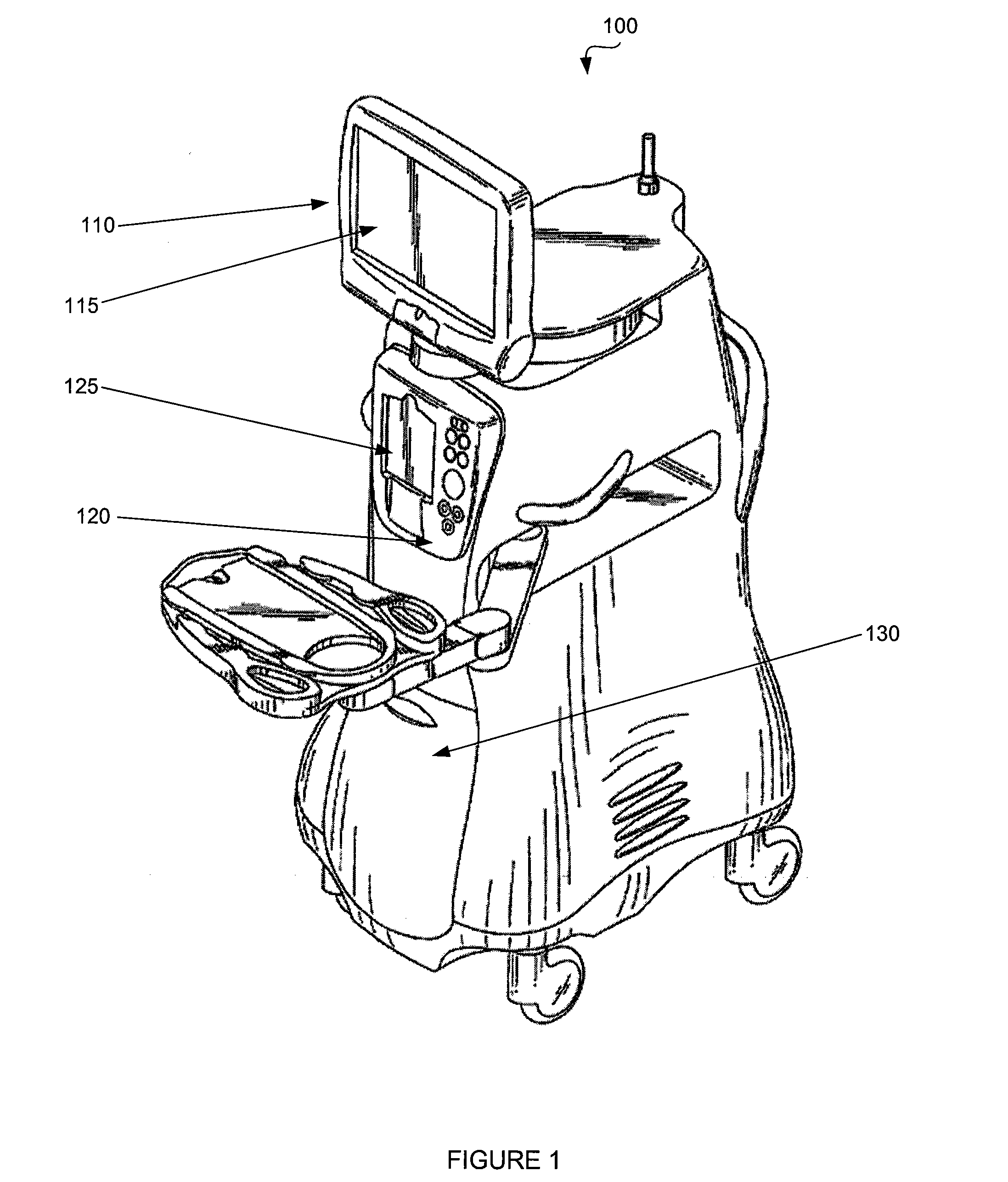
[0018]FIG. 1 is a diagrammatic representation of one embodiment of an ophthalmic surgical console 100. Surgical console 100 can include a swivel monitor 110 that has touch screen 115. Swivel monitor 110 can be positioned in a variety of orientations for whomever needs to see touch screen 115. Swivel monitor 110 can swing from side to side, as well as rotate and tilt. Touch screen 115 provides a graphical user interface (“GUI”) that allows a user to interact with console 100.

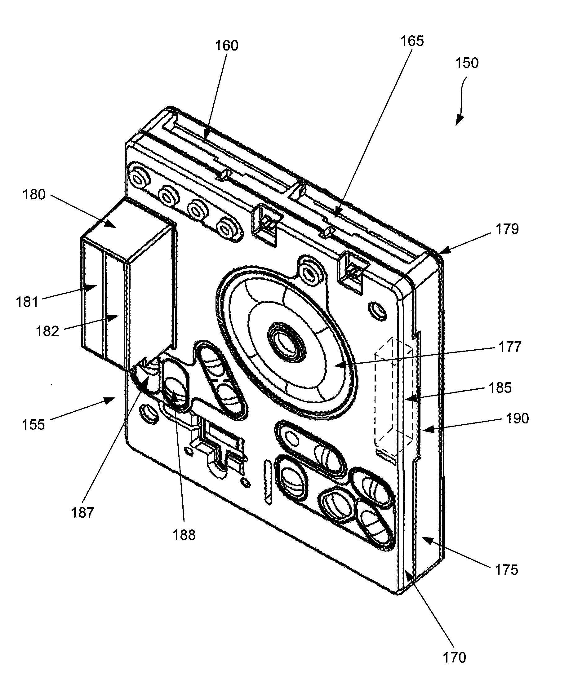
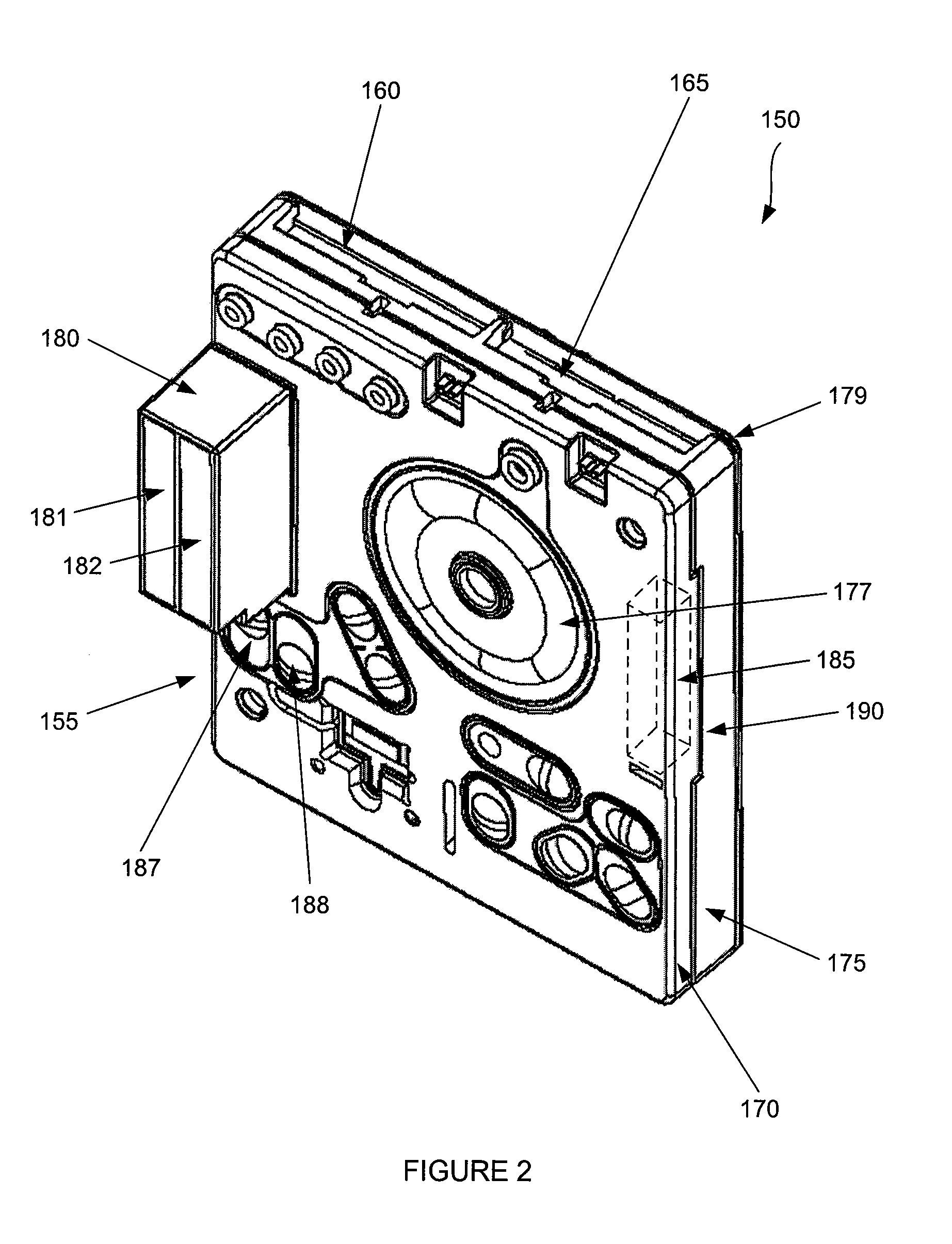
[0019]Surgical console 100 also includes a connection panel 120 used to connect various tools and consumables to surgical console 100. Connection panel 120 can include, for example, a coagulation connector, connectors for various hand pieces, and a cassette receiver 125. Surgical console 100 can also include a variety of user friendly features, such...


PUM


Abstract

Embodiments of the present invention provide an apparatus and method controlling the flow of aspiration fluid in an aspiration chamber of a surgical cassette. One embodiment of the present invention provides an aspiration chamber having an aspiration port positioned at or close to the bottom of the chamber. When the aspiration fluid enters the aspiration chamber from below the fluid surface (e.g., from a port located at the bottom or on a sidewall close to the bottom), it does not create disturbance at the liquid / air interface and thus does not disturb the continuous level sensing. Also, since the aspiration port is placed at or very close to the bottom of the aspiration chamber, the liquid inside the chamber can be fully used for sustained reflux and push priming.

Description

TECHNICAL FIELD OF THE INVENTION[0001]The present invention relates to surgical systems and methods. More particularly, the present invention relates to systems and methods for controlling fluid flow. Even more particularly, embodiments of the present invention relate to systems and methods for controlling the flow of fluid entering from the bottom of an aspiration chamber in a surgical system.BACKGROUND OF THE INVENTION[0002]The human eye can suffer a number of maladies causing mild deterioration to complete loss of vision. While contact lenses and eyeglasses can compensate for some ailments, ophthalmic surgery is required for others. Generally, ophthalmic surgery is classified into posterior segment procedures, such as vitreoretinal surgery, anterior segment procedures, such as cataract surgery, and combined anterior and posterior segment procedures.[0003]The surgical instrumentation used for ophthalmic surgery can be specialized for posterior segment procedures or anterior segmen...

Claims


Application Information

Patent Timeline
IPC IPC(8): A61M1/00
CPCA61M1/0023A61M2205/3389A61M2205/12A61M1/72A61M1/76A61M1/73A61M1/74A61M1/77A61M3/0201A61F9/00736
Inventor HOPKINS, MARK ALANGAO, SHAWN X.
Owner NOVARTIS AG
Why Eureka
Try Eureka