Control microcomputer verification device and vehicle-mounted control device

a microcomputer and verification device technology, applied in the direction of error detection/correction, instruments, computing, etc., can solve the problems of inability to determine the quality and reliability of control software in reality, the overall quality and reliability cannot be fully assured, and the control software behaves in an unexpected manner. achieve the effect of high verification efficiency

Inactive Publication Date: 2008-06-19
HITACHI LTD
View PDF15 Cites 21 Cited by
  • Summary
  • Abstract
  • Description
  • Claims
  • Application Information

AI Technical Summary

Benefits of technology

[0032]The control microcomputer verification device according to the present invention makes it possible to add an assertion-based verification function concerning control software or the entire system and perform verification with high verification efficiency without imposing an increased load on the microcomputer to be verified or on the control software.

Problems solved by technology

However, since it is an advance design technology, it does not assume the verification in the actual operational settings.
Further, no matter how an advance design is made strictly, overall quality and reliability cannot be fully assured unless verification is performed through actual operations, which is governed by the god of physics.
Further, if a wrong internal state is designated as a transition destination, the control software also behaves in an unexpected manner during an actual operation.
It is common knowledge that even if internal state definitions, state transition conditions (events), and actions to be taken during the transition are elaborately designed in advance, the quality and reliability of control software cannot be determined in reality unless the behavior of the control software is monitored and verified during an actual operation.

Method used


Image

  • Control microcomputer verification device and vehicle-mounted control device
  • Control microcomputer verification device and vehicle-mounted control device
  • Control microcomputer verification device and vehicle-mounted control device

Examples


Embodiment Construction

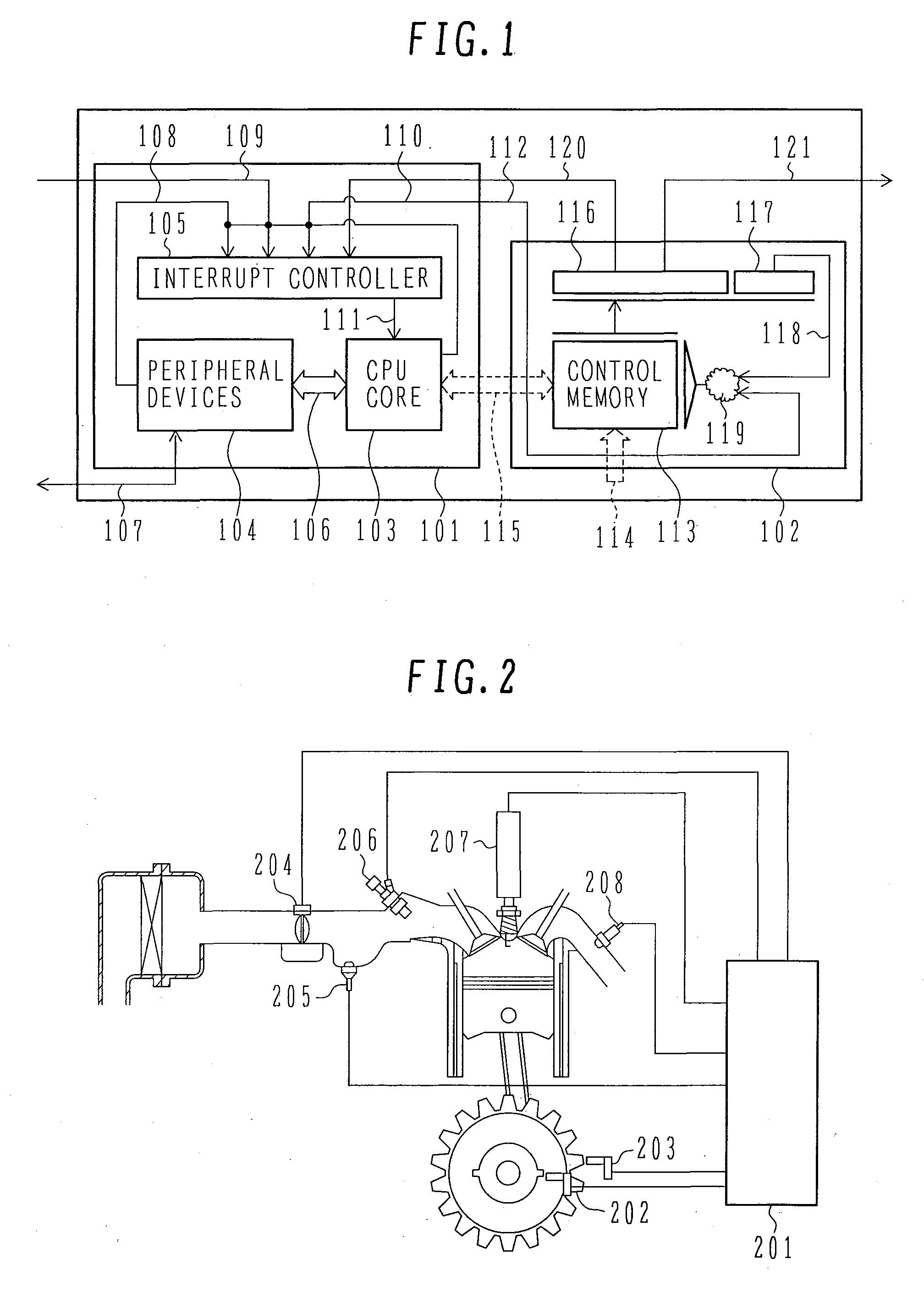
[0044]FIG. 1 shows an embodiment of a control microcomputer verification device according to the present invention and a microcomputer for sequentially executing the control software to be verified.

[0045]The microcomputer 101 is a control microcomputer that sequentially executes the control software to be verified. The microcomputer 101 includes, for instance, a CPU core 103 for interpreting and executing the control software, a peripheral device 104 that is connected to the CPU core 103 via an internal bus 106, and an interrupt controller 105 as essential functional blocks.

[0046]For example, a general-purpose timer unit, analog-to-digital converter, or communication module (none of these components are shown in the figure) may be employed as the peripheral device 104. The peripheral device 104 exchanges information with the outside via an input / output signal line 107.

[0047]Timing information 108 about a series of events handled by the peripheral device 104, such as a compare match ...


PUM


Abstract

The present invention offers an advanced control software verification technology, particularly, an assertion-based verification technology, by providing a control microcomputer verification device and vehicle-mounted control device that exhibit improved verification efficiency. Assertion-based verification is performed with a verification device that has a hardware configuration in which the verification device is independent of a CPU core of a microcomputer but operates in parallel with the CPU core of the microcomputer, which sequentially executes control software. The hardware to be employed to achieve the above purpose is a finite state machine based on microprogrammed control. An interrupt factor is branched immediately before an interrupt controller for the microcomputer and used as a transition input. When an abnormal transition is detected, a warning is output to the microcomputer as an interrupt or output to the outside in the form of a signal.

Description

BACKGROUND OF THE INVENTION[0001]1. Field of the Invention[0002]The present invention relates to a control microcomputer verification device and vehicle-mounted control device, and more particularly to a verification device and vehicle-mounted control device that are used to perform assertion-based verification (ABV) of state transition caused by control software, which is sequentially executed by a microcomputer.[0003]2. Description of the Related Art[0004]In recent years, it is demanded that in-vehicle control software exhibit enhanced operation reliability due to an increased use of electronic machine parts. It goes without saying that the required level for software functional accuracy and the design level for design system strictness are raised in accordance with the above demand.[0005]In particular, the design of state transition within a control algorithm is a problem. A state transition design must be made so that an external phenomenon is flexibly coped with in relation to ...

Claims


Application Information

Patent Timeline
Patent Type & Authority Applications(United States)
IPC IPC(8): G06F11/28G06F13/24G06F11/30
CPCG06F11/0739G06F11/0736G06F11/14G06F11/0751
Inventor MIYAKE, JUNJI
Owner HITACHI LTD
Why Eureka
Try Eureka