Method of verifying component functionality on egr & air systems

a technology of component functionality and air system, applied in the field of method of verifying component functionality on egr & air system, can solve problems such as rationality checks, adversely affecting emissions, and operating within their normal range but not longer accura

Active Publication Date: 2008-06-26
DETROIT DIESEL CORP
View PDF3 Cites 64 Cited by
  • Summary
  • Abstract
  • Description
  • Claims
  • Application Information

AI Technical Summary

Benefits of technology

[0003]In one aspect, the present invention includes a method for operating an electronically controlled internal combustion engine in a vehicle to perform at least one rationality check on at least one sensor to detect impending sensor failure and verify component functionality. The engine is usually equipped with a electronic control unit (ECU) having a memory. The engine control system (ECS) may consist of multiple ECUs. For example, it may be a two controller system comprised of a Motor Control Module (MCM) and a Common Powertrain Controller (CPC) interface in data link communication with each other and the sensors. The MCM is in electronic communication with various sensors on the engine and it receives additional vehicle compone...

Problems solved by technology

Sensors not exhibiting hard circuit failures may adversely affect emissions as a result of in-range failures of sensors.
The rationality checks are i...

Method used


Image

  • Method of verifying component functionality on egr & air systems
  • Method of verifying component functionality on egr & air systems
  • Method of verifying component functionality on egr & air systems

Examples


Embodiment Construction

)

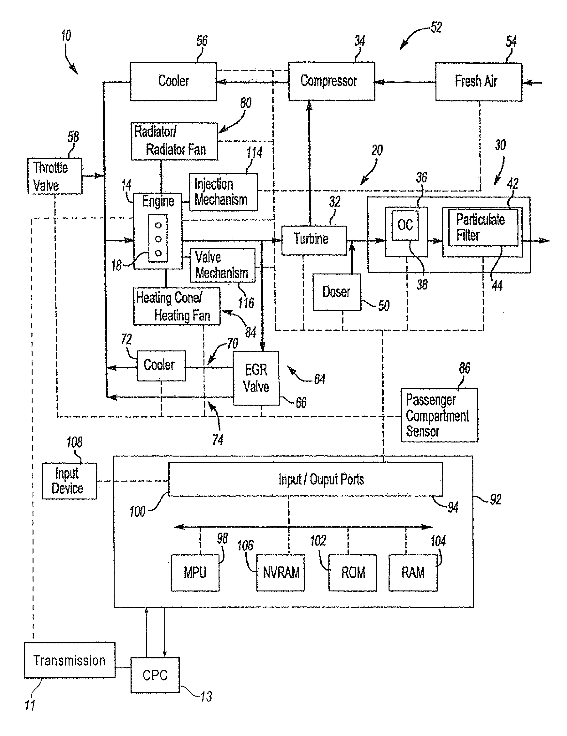
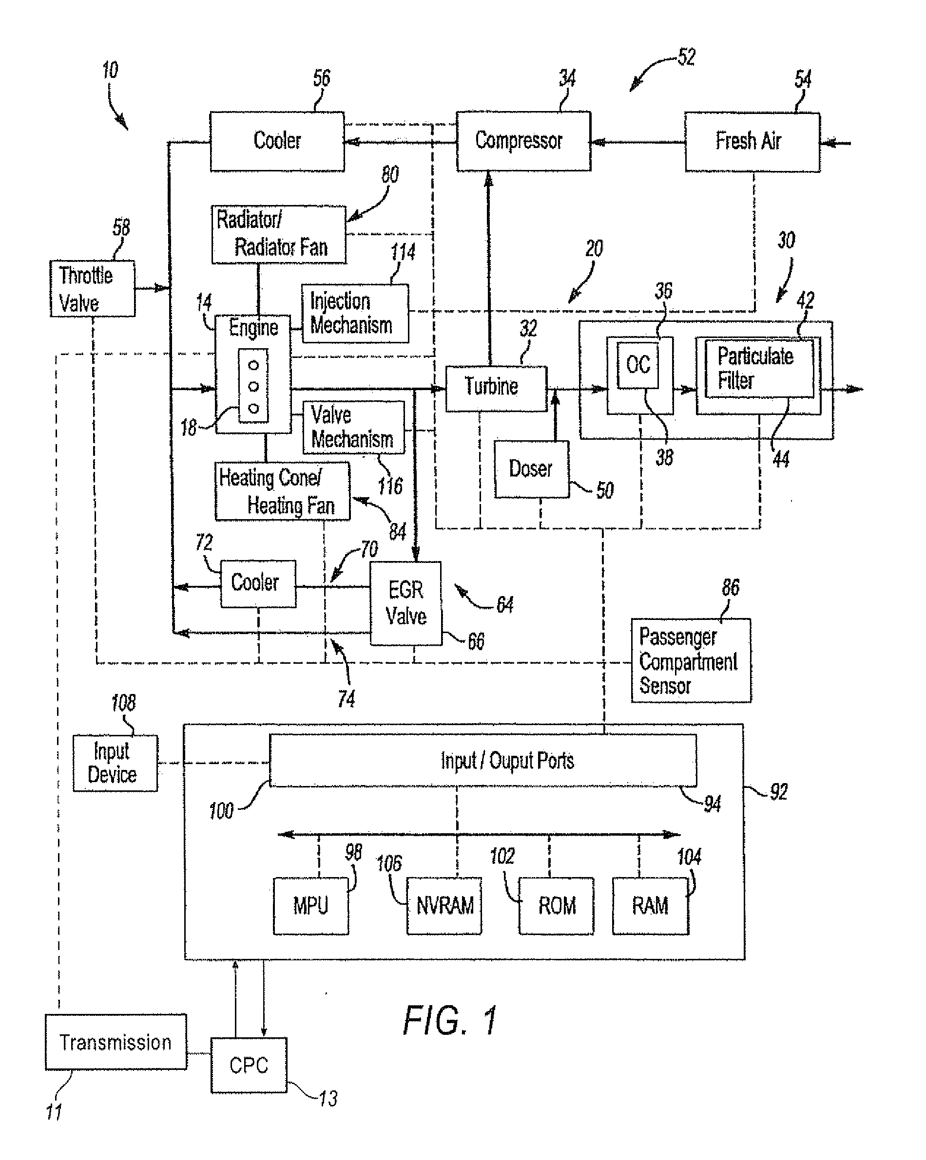
[0017]FIG. 1 illustrates a vehicle powertrain system 10 in accordance with one non-limiting aspect of the present invention. The system 10 may provide power for driving any number of vehicles, including on-highway trucks, construction equipment, marine vessels, stationary generators, automobiles, trucks, tractor-trailers, boats, recreational vehicle, light and heavy-duty work vehicles, and the like.

[0018]The system 10 may be referred to as an internal combustion driven system wherein fuels, such as gasoline and diesel fuels, are burned in a combustion process to provide power, such as with a spark or compression ignition engine 14. The engine 14 may be a diesel engine that includes a number of cylinders 18 into which fuel and air are injected for ignition as one skilled in the art will appreciate. The engine 14 may be a multi-cylinder compression ignition internal combustion engine, such as a 4, 6, 8, 12, 16, or 24 cylinder diesel engines, for example. It should be noted, however, ...


PUM


Abstract

In one aspect, the present invention is directed to a method for operating an electronically controlled internal combustion engine in a vehicle to perform at least one rationality check on at least one sensor to detect impending sensor failure and verify component functionality. The engine is equipped with an engine control system (ECS) having a memory and in electronic communication with various sensors. The sensors transmit data signals to the ECS indicative of associated engine and vehicle component functionality. The method comprises determining a measured operating condition of a first component from sensor data signals indicative of first component functionality, determining a measured operating condition of a second component from sensor data signals indicative of second component functionality, comparing the measured condition of the first component to the measured operating condition of the second component to determine whether sensor readings from the first component are indicative of a component operating within a normal range but indicative of impending sensor or component failure, logging an indication of an impending sensor or component failure as a fault in MPU memory if it occurs for a predetermined period of time and for more than a predetermined number of times and drive cycles, and activating a warning alert to an operator and initiating remedial actions responsive to the indication of impending component or sensor failure. The data logged includes time of fault, type of fault, number of occurrences of the fault, number of drive cycles where the fault occurred and distance traveled with the fault logged.

Description

CROSS-REFERENCE TO RELATED APPLICATIONS[0001]The present application claims priority of provisional patent application 60 / 876,664 field Dec. 22, 2006 entitled “Method of Verifying Component Functionality on EGR & Air Systems”.TECHNICAL FIELD OF THE INVENTION[0002]Current engine controller software provides circuit diagnostics (failed high, short to battery, short to ground) for all input sensors. Sensors not exhibiting hard circuit failures may adversely affect emissions as a result of in-range failures of sensors. Recent legislation requires that these in-range failures of emission related inputs be detected and the engine operated accordingly so that the impending failure is noted and attended to by service personnel. The present invention is directed to a method to implement rationality checks for detecting and managing in-range failures of emissions related inputs. The rationality checks are intended to identify components that are still operating within their normal range but a...

Claims


Application Information

Patent Timeline
IPC IPC(8): G01M15/04G06F19/00G01M17/00
CPCG01M15/05
Inventor KESKI-HYNNILA, DONALD E.HAWKINS, JEFFERY S.WEDLER, HARALDPFUNDT, REINHARDGROER, FRANK S.ZURAWSKI, MARK A.GRACE, DENNIS J.STALEY, HEATHER A.PRIEST, JIMMIE L.SUN, MINBARTON, JASON T.HAN, ZHIPING
Owner DETROIT DIESEL CORP
Why Eureka
Try Eureka