Packaging and application device

a packaging and application technology, applied in the field of packaging and application devices, can solve the problems of numerous parts to be manufactured and assembled, product residue may remain, and the device does not make it possible to easily replace an empty container with a new one, so as to avoid or reduce the possibility of product contamination, avoid or reduce the presence of stagnant product residues, and facilitate manufacturing and assembly.

Active Publication Date: 2008-06-26
LOREAL SA
View PDF36 Cites 25 Cited by
  • Summary
  • Abstract
  • Description
  • Claims
  • Application Information

AI Technical Summary

Benefits of technology

[0017]One object of the present invention is to provide a device that is easy to manufacture and to assemble.
[0018]In particular, one object of the present invention is to provide a rechargeable device which avoids or reduces the possibility of products contamination. One object of the present invention is especially to avoid or reduce the presence of stagnating product residues resulting from a previous use of the device.
[0020]One object of the present invention is also to provide a device having an actuating movement that is original and comfortable for the user.
[0025]Further by way of example, the actuating walls and the application surfaces may extend in the length, or along a major axis, of a transverse cross section of the device. Actuation of the device and the application of product therefrom are thus facilitated. For actuation, the user can grip a container using all their fingers without interfering with the other container. Thus, the user may compress one container with one hand and the other container with their other hand. In order to do this, the user may position their thumb on one side wall of a container and at least one of their other fingers on an opposite side wall of this same container. A compression in a direction to bring together their thumb and at least one of their other fingers makes it possible to start dispensing product from this container. By releasing the digital pressure exerted on these walls, the container may then return to its initial configuration. In this maneuver, the actuating of one container absolutely does not interfere with the other container.
[0049]Such a device can facilitate the actuation of the first and second containers and thus enable better metering of the products dispensed.
[0061]The branches can thus keep the container bodies, and also optionally their associated nozzle(s), joined together. Such branches can leave at least one lateral surface of each container free, or even two opposite lateral surfaces of each container. A user can thus bring their fingers directly in contact with the respective lateral surfaces of the container so as to compress the container in order to dispense product.

Problems solved by technology

However, one drawback associated with this device is that it consists of numerous parts to be manufactured and assembled.
However, each time a product is dispensed, a residue of product may remain in the dispensing channel.
Thus, if one container is replaced by a container that contains a different product, the product dispensed from this new container may be soiled by the old product coating the dispensing channel.
Furthermore, it is clear that such a device does not make it possible to easily replace an empty container with a new container.
However, one drawback associated with this device is that it does not provide for dispensing of one product from one container independently of the product contained in the other container.
In addition, the dispensing of products simultaneously may result in a reciprocal contamination of the product dispensed which may not be desired in certain cases, especially when one product must be applied before the other.
However, one drawback associated with this device is that the positioning of the dispensing head on the two containers causes an inclination of the dispensing channels in the direction of the dispensing orifice.
Thus, when a manual pressure exerted on one container is stopped, the product dispensed through one dispensing channel may easily flow back toward the other dispensing channel and thus contaminate the other container.
Moreover, product dispensed from one container may remain stagnant in the common dispensing head and may thus contaminate a newly dispensed product.

Method used


Image

  • Packaging and application device
  • Packaging and application device
  • Packaging and application device

Examples


Embodiment Construction

[0106]Referring now to the drawings, like reference numerals are utilized to designate identical or corresponding parts throughout the several views.

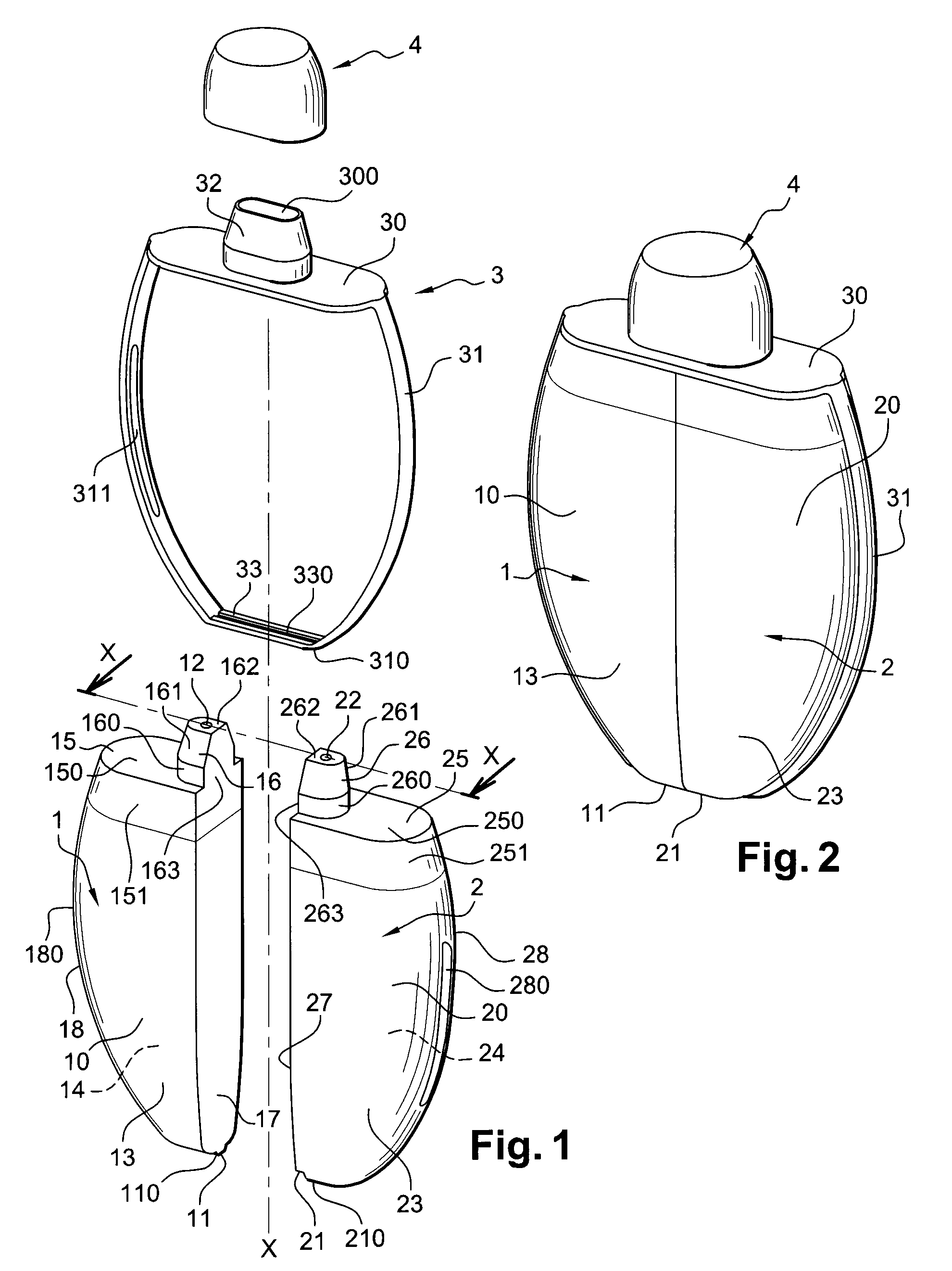
[0107]With reference to FIGS. 1 and 2, an example of a packaging and application device according to the present invention includes a first container 1, a second container 2 and a coupling device 3. This coupling device includes a coupling means or coupling arrangement 3 that are added on or mounted to make it possible to firmly attach the first and second containers 1 and 2 together.

[0108]In the illustrated example, the first and second containers 1, 2 both have an identical configuration. The containers 1, 2 can be produced from an identical or different material. This material can be a polyolefin such as polypropylene, low-density polyethylene or high-density polyethylene, for example. The first and second containers can be produced, for example, by blending by injection blow molding or from various layers of various materials by ext...


PUM


Abstract

A packaging and application device includes a first container which can contain a first product, with the first container including a deformable wall, so as to enable the first product to be dispensed through a first dispensing orifice. The device further includes a second container which can contain a second product, with the second container including a deformable wall, so as to enable the second product to be dispensed through a second dispensing orifice. According to an example, a coupling arrangement is mounted on the containers and joins the first and second containers together. The first and second dispensing orifices emerge separately at the level of a first application surface and a second application surface respectively, and the first and second containers are configured so as to be able to be actuated independently of one another.

Description

CROSS-REFERENCE TO RELATED APPLICATIONS[0001]This document claims priority to French Application Number 06 55780, filed Dec. 21, 2006 and U.S. Provisional Application No. 60 / 883,282, filed Jan. 3, 2007, the entire contents of which are hereby incorporated by reference.BACKGROUND OF THE INVENTION[0002]1. Field of the Invention[0003]The present invention relates to a device for packaging and applying at least one cosmetic product. One favored, but not exclusive, application of the present invention is for the application of a mixture of cosmetic products to an area of the body such as the lips, eyelids, cheeks or nails. The expression “cosmetic product” is understood to mean a product such as defined in Council Directive 93 / 35 / EEC of 14 Jun. 1993.[0004]2. Discussion of Background[0005]Many devices that make it possible to store various cosmetic products to be mixed extemporaneously (when use is desired) for the purpose of applying this mixture to an area of the body are listed in the ...

Claims


Application Information

Patent Timeline
Patent Type & Authority Applications(United States)
IPC IPC(8): A45D34/00B65D83/00B05B11/00
CPCB65D81/3288
Inventor ABERGEL, ALINE
Owner LOREAL SA
Why Eureka
Try Eureka