Irradiation Pattern Data Generation Method, Mask Fabrication Method, and Plotting System

a mask fabrication and pattern technology, applied in the field of irradiation pattern data generation method, mask fabrication method, plotting system, can solve the problems of reducing the plotting time, affecting the accuracy of the plotting method, and unable to achieve sufficient resolving power in the raster scan mode, so as to reduce the plotting time

Inactive Publication Date: 2008-06-26
RAMBUS INC
View PDF8 Cites 15 Cited by
  • Summary
  • Abstract
  • Description
  • Claims
  • Application Information

AI Technical Summary

Benefits of technology

[0038]The present invention provides an irradiation pattern data generation method, a mask fabrication method, and a plotting system that can reduce the plotting time.
[0039]The present invention further provides an irradiation pattern data generation method, mask fabrication method, and plotting system that do not increase the number of rectangles when carrying out process bias correction.

Problems solved by technology

However, the difficulty of implementing optical proximity effect correction in the raster scan method necessitates the use of an electron beam of relatively low acceleration voltage (on the order of, for example, 20 keV) that does not exhibit the influence of the proximity effect.
Obtaining sufficient resolving power in the raster scan mode is problematic due to the use of an electron beam of relatively low acceleration voltage.
When using the variable rectangle method, however, the plotting time can become time-consuming in some cases.
In particular, the inclusion of a pattern that extends diagonally in the design pattern results in division into a multiplicity of extremely minute rectangles in the irradiation pattern, whereby the plotting time becomes extremely long.
The dimensional accuracy during plotting may fall when the form of the rectangles becomes extremely minute.
Irradiating an electron beam in such minute rectangles r2 is disadvantageous from the standpoint of dimensional accuracy.

Method used


Image

  • Irradiation Pattern Data Generation Method, Mask Fabrication Method, and Plotting System
  • Irradiation Pattern Data Generation Method, Mask Fabrication Method, and Plotting System
  • Irradiation Pattern Data Generation Method, Mask Fabrication Method, and Plotting System

Examples


first embodiment

[0056]Explanation next regards the first embodiment with reference to the accompanying drawings.

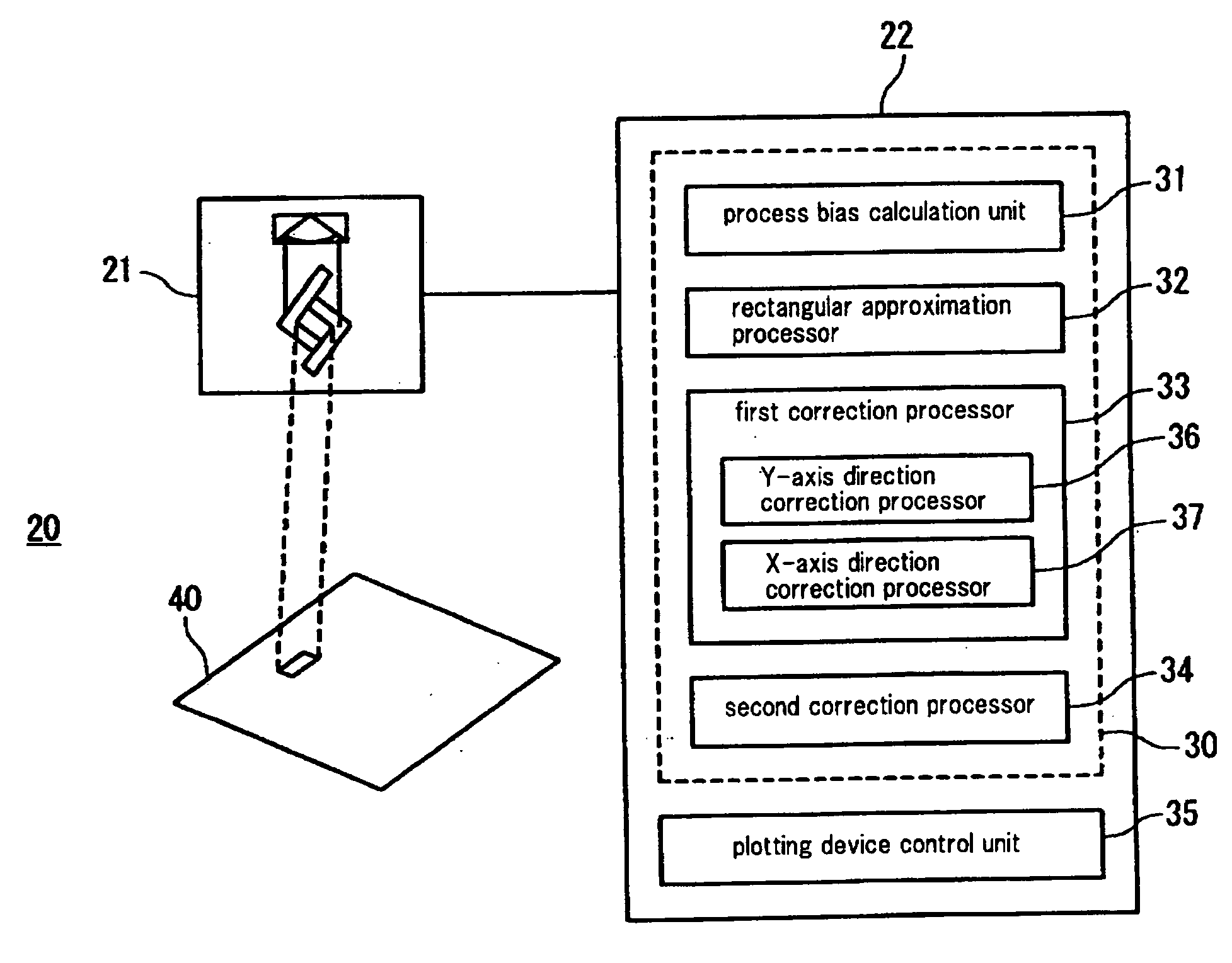
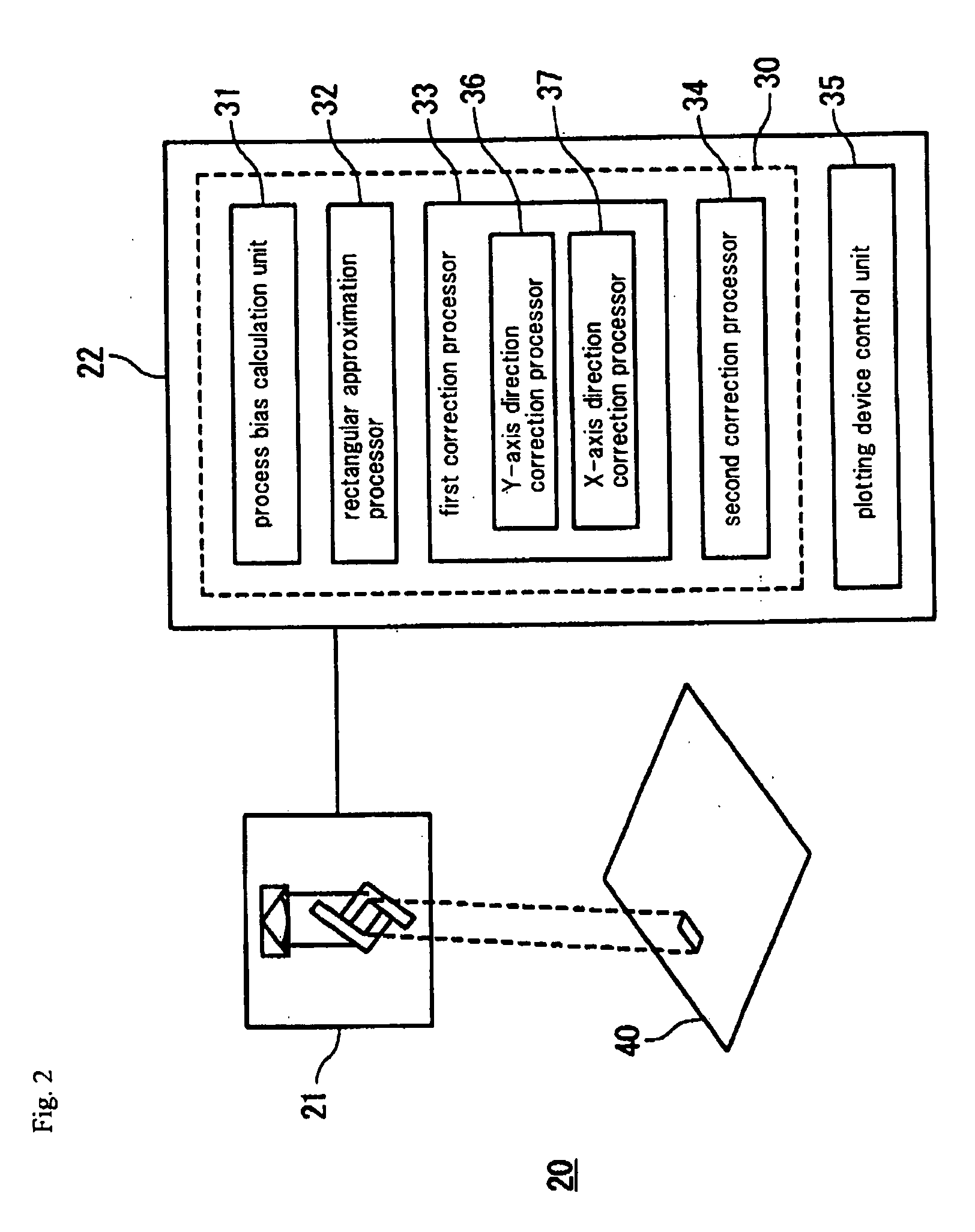
[0057]FIG. 2 is a schematic view of the configuration of plotting system 20 of the present embodiment. As shown in FIG. 2, plotting system 20 includes plotting device 21 and control device 22. Plotting device 21 is a device for irradiating an electron beam upon object of plotting 40 to carry out plotting. Control device 22 generates the pattern (irradiation pattern) of the beam that is irradiated by plotting device 21 and controls the operation of plotting device 21. In addition, the generation of the irradiation pattern and the control of the operation of plotting device 21 need not be carried out in a single device, but may be implemented by separate devices.

[0058]By way of example, control device 22 is shown as a computer that includes RAM (Random Access Memory) and ROM (Read Only Memory), a CPU, and a hard disk. Irradiation pattern generation program 30 and plotting device control uni...

second embodiment

[0089]Explanation next regards the second embodiment. In the configuration of the plotting system of the present embodiment, the functional configuration of irradiation pattern generation program 30 differs from that of the first embodiment. Components having the same functional configuration as the first embodiment are given the same reference numbers and explanation of these items may be here omitted.

[0090]FIG. 12 is a block diagram showing the content of irradiation pattern generation program 50 of the present embodiment. Irradiation pattern generation program 50 includes process bias calculation unit 51, rectangular approximation processor 52, and bias correction processor 53. In addition, the functions of process bias calculation unit 51 are the same as process bias calculation unit 51 in the first embodiment, and explanation of this part is therefore here omitted. However, the functions of rectangular approximation processor 52 differ from those of rectangular approximation pr...


PUM

PropertyMeasurementUnit
widthaaaaaaaaaa
widthaaaaaaaaaa
lengthaaaaaaaaaa

Abstract

An irradiation pattern data generation method includes: a process for providing a design pattern having diagonal side portions that extend diagonally with respect to an X-axis direction and a Y-axis direction on an XY plane; a rectangular approximation process for approximating the design pattern to rectangles to generate a rectangular approximation pattern; a first correction process for shifting the side portions of the rectangular approximation pattern in the Y-axis direction to generate a first correction pattern; and a second correction process for enlarging the side portions of the first correction pattern in the X-axis direction and the Y-axis direction to generate an irradiation pattern.

Description

[0001]This application is based upon and claims the benefit of priority from Japanese Patent Application No. 2006-274779 filed on Oct. 6, 2006, the content of which is incorporated by reference.BACKGROUND OF THE INVENTION[0002]1. Field of the Invention[0003]The present invention relates to an irradiation pattern data generation method and plotting system used in irradiating energy upon an object of plotting to carry out plotting, and to a method of fabricating a photomask formed by the plotting system.[0004]2. Description of the Related Art[0005]Techniques are known for using a plotting device to irradiate energy such as an electron beam to form a desired pattern on an object of plotting. Such techniques are applied in, for example, the manufacture of photomasks used in the photolithographic steps in the fabrication process of semiconductors.[0006]A raster scan method and a variable rectangle method are known as methods of such a plotting device. The raster scan method is a plotting...

Claims


Application Information

Patent Timeline
Patent Type & Authority Applications(United States)
IPC IPC(8): G21K5/10G03F1/00G03F1/76G03F1/78G03F7/20H01L21/027
CPCB82Y10/00B82Y40/00H01J37/3174G03F7/2063H01J37/3026G03F1/78G03F1/68
Inventor YASUZATO, TADAO
Owner RAMBUS INC
Why Eureka
Try Eureka