Base design of cooling structure

a cooling structure and base design technology, applied in the direction of machines/engines, stators, liquid fuel engines, etc., can solve the problems of non-uniform contraction stress, non-uniform contraction stress, deformation of the base of the conventional cooling structure, etc., to prevent non-uniform contraction stress, reduce product defective rate, and prolong the life of the product

Inactive Publication Date: 2008-06-26
SUNONWEALTH ELECTRIC MACHINE IND
View PDF2 Cites 7 Cited by
  • Summary
  • Abstract
  • Description
  • Claims
  • Application Information

AI Technical Summary

Benefits of technology

[0010]The present invention employs the groove design to effectively prevent the non-uniform contraction stress caused by difference of cooling time and temperature and thus to prevent a slanted shaft tube so as to support stable rotation of the spindle of the impeller, and to avoid the issues of run-out and noise, thereby ensuring that vibration and noise test value of the product comply with a standard value range, the product defective rate is lowered and the lifespan of the product is prolonged at the same time.

Problems solved by technology

Whereas, when the base of the conventional cooling structure is formed by injection molding or die-casting, it is easily subjected to a contracted intrinsic stress and deformed, thus resulting in the following drawbacks;
Hence, non-uniform contraction stresses arises from such difference, and the base of the conventional cooling structure is easily prone to a deformation resulting from the non-uniform contraction stresses, which gives rise to an oblique center line of the shaft tube.
large rotational run-out of impeller and large noise: As the base of the conventional cooling structure is easily subjected to the effect of the contraction stress, the shaft tube tends to be deflected and slanted.
Consequently, when the impeller rotates, the slanted angle will make the impeller generate serious run-out, which also accompanies with a wind shear effect to generate enormous noise.
high product defective rate: When the impeller, because of the slanted shaft tube, generates serious run-out and enormous noise, the most direct impact is certainly a significant increase of product vibration and noise test value that sometimes even exceed a standard value range and thus result in a higher product defective rate.
short lifespan: When the impeller of the cooling structure is positioned in an environment with high run-out and high vibration amplitude for a long period of time, the life duration of the structure itself could be worn out seriously.
Above all, the spindle and the bearing will be worn out much faster for withstanding the run-out and thus shorten the lifespan of the cooling structure.

Method used


Image

  • Base design of cooling structure
  • Base design of cooling structure
  • Base design of cooling structure

Examples


Embodiment Construction

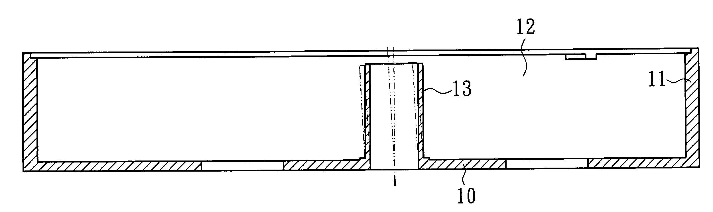
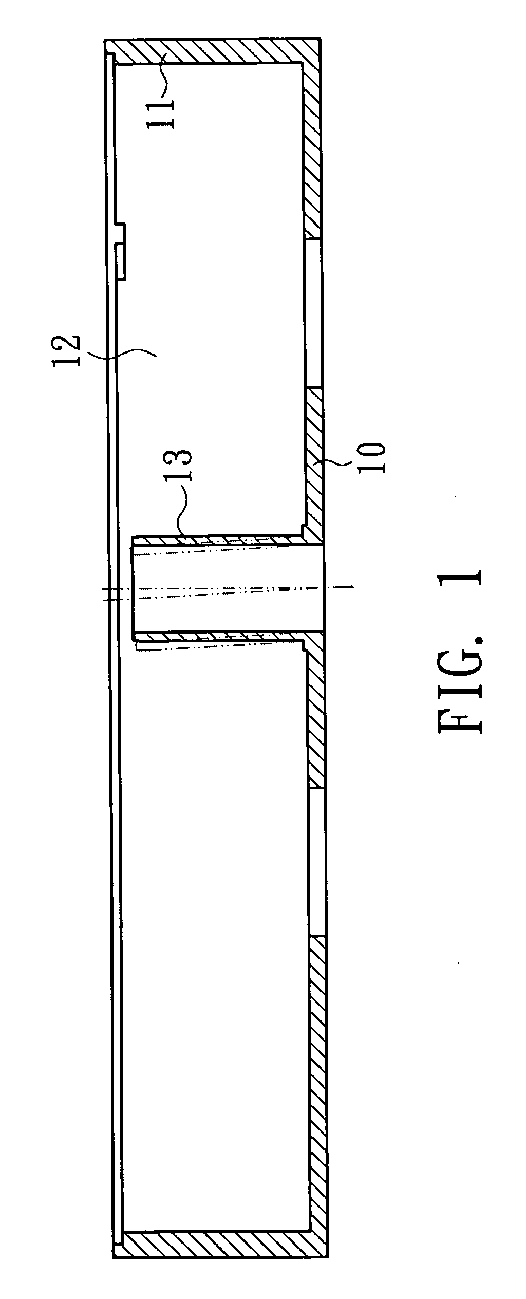
[0021]The present invention relates to a base design of cooling structure, including a groove disposed on the base, in which the groove is located beyond the reach of an outer diameter of a shaft tube. The groove design is employed to effectively prevent the impact of thermal contraction stress on the shaft tube and prevent the shaft tube from tilting to enhance the quality and the lifespan of the product.

[0022]Illustrated are few preferred embodiments of the present invention.

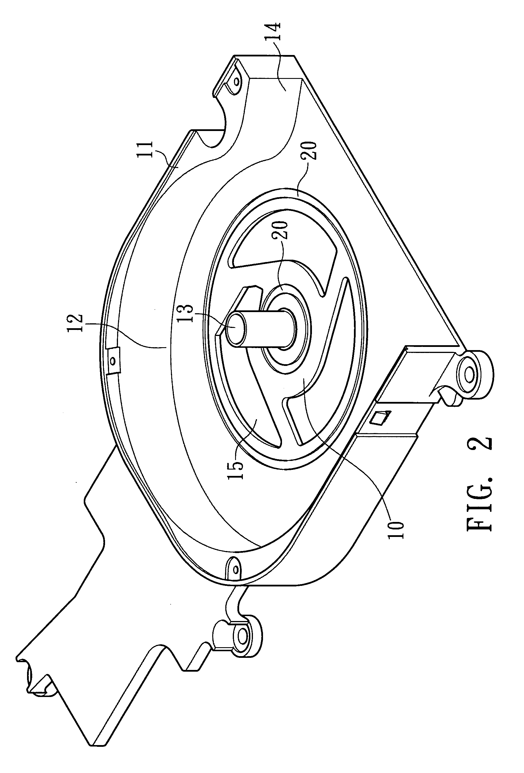
[0023]As shown in FIG. 2. and FIG. 3, a first preferred embodiment of the present invention includes a base 10, in which a containing space 12 is surrounded by a side wall 11 on the periphery of the base excluding an air outlet side 14, an impeller and a stator set (not shown in FIGS. 2 & 3) and a shaft tube 13 are disposed inside the containing space 12, the shaft tube 13 can be assembled or integrally formed on the base 10, and a bearing is placed in a center bore of the shaft tube 13 for supporting a spindl...


PUM


Abstract

The present invention relates to a base design of cooling structure, which includes a base, and a shaft tube disposed on the base to support a spindle of an impeller to rotate therein. The base has at least a groove and the groove is located beyond an outer diameter; the groove design can be employed to effectively prevent the issue of contraction stress caused by difference of cooling time of temperature and to prevent a slanted shaft tube for supporting a stable operation of the spindle of the impeller, thereby avoiding the resulting run-out and noise, making vibration and noise test values of the product comply with a standard value range, reducing the defective rate of the product and prolonging the product lifespan.

Description

FIELD OF THE INVENTION[0001]The present invention relates to a base design of cooling structure, which can effectively prevent the center axis from being deviated due to the intrinsic stress out of thermal contraction of the base, so as to address a practical structure securing the quality and the lifespan of the product.BACKGROUND OF THE INVENTION[0002]As shown in FIG. 1, a conventional cooling structure includes a base 10 having an containing space 12 surrounded by a side wall 11 on a periphery thereof, an impeller and a stator set (not shown in FIG. 1, as the driving relationship between the impeller and the stator set is irrelevant to the subject of the present invention, both parts are not further depicted here), a shaft tube 13 disposed in the containing space 12, assembled or integrally formed on the base 10, providing a center bore for accommodating a bearing that supports a spindle of the impeller to rotate therein.[0003]Whereas, when the base of the conventional cooling st...

Claims


Application Information

Patent Timeline
Patent Type & Authority Applications(United States)
IPC IPC(8): F04D29/52
CPCF04D29/056F04D29/668F04D29/626F04D29/582F04D25/062
Inventor HORNG, ALEXLI, TUNG CHENG
Owner SUNONWEALTH ELECTRIC MACHINE IND
Why Eureka
Try Eureka