Wafer dividing method
a technology of dividing method and wafer, which is applied in the direction of manufacturing tools, welding/soldering/cutting articles, and semiconductor/solid-state device details. it can solve the problems of reducing the quality of devices, and reducing the detection efficiency of devices. it can prevent the formation of obtained devices from being detected
- Summary
- Abstract
- Description
- Claims
- Application Information
AI Technical Summary
Benefits of technology
Problems solved by technology
Method used
Image
Examples
first embodiment
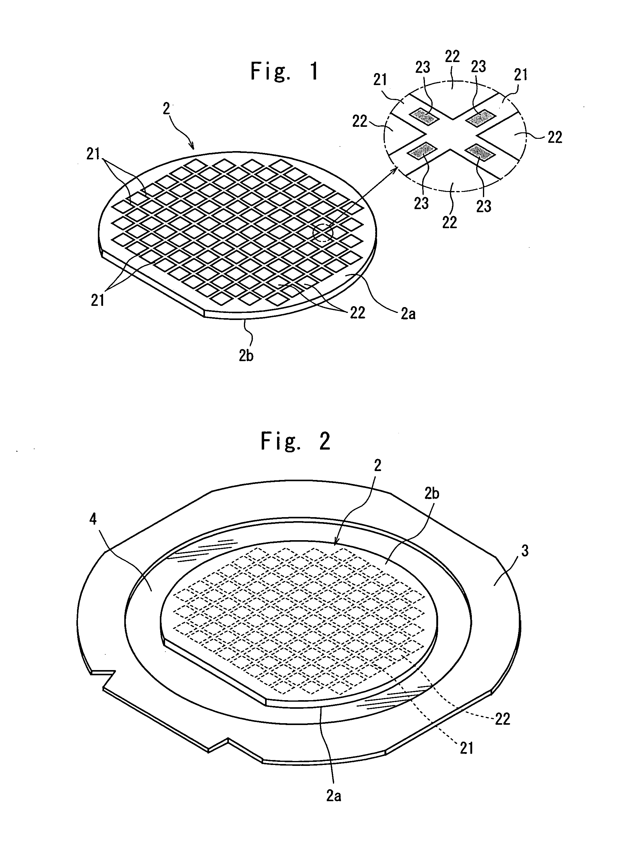
[0038]A description will be first given of the method of dividing the semiconductor wafer 2 along the plurality of streets 21.
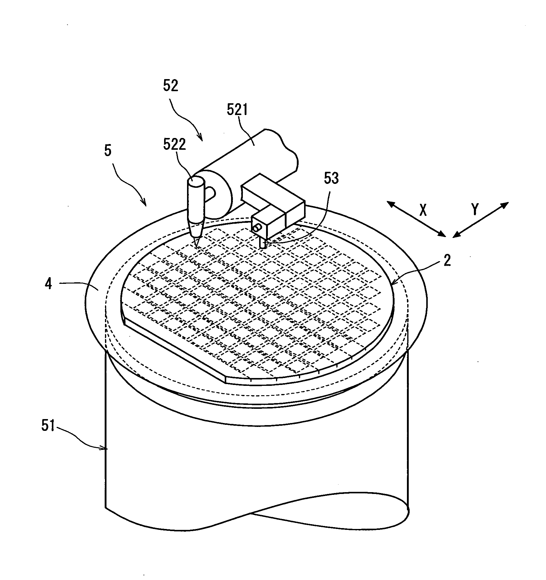
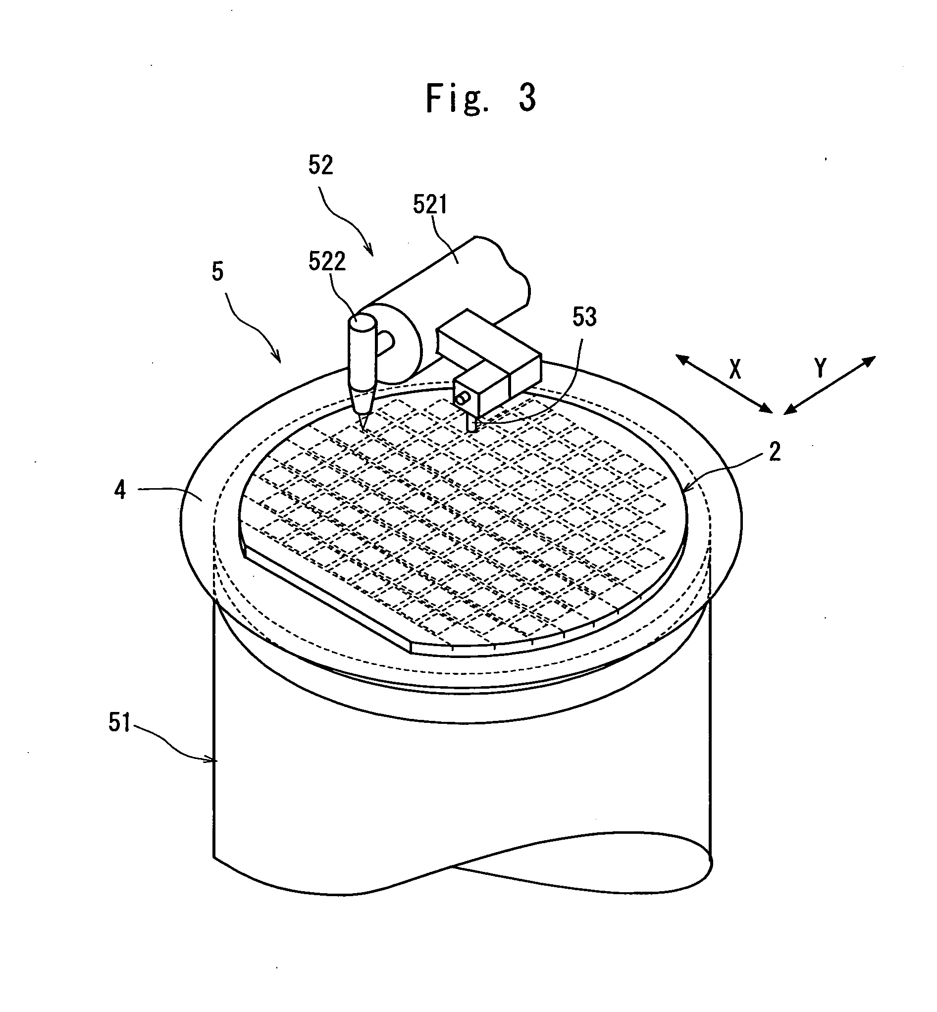
[0039]First comes a laser beam application step for carrying out laser processing by applying a laser beam along a street 21 on both sides of the test metal patterns 23 in the street 21 formed on the semiconductor wafer to form a dividing start point along the street 21 on both sides of the test metal patterns 23. This laser beam application step is carried out by using a laser beam processing machine shown in FIG. 3. The laser beam processing machine 5 shown in FIG. 3 comprises a chuck table 51 for holding a workpiece and laser beam application means 52 for applying a laser beam to the workpiece held on the chuck table 51. The chuck table 51 is so constituted as to suction-hold the workpiece and is designed to be moved in a processing-feed direction indicated by an arrow X in FIG. 3 by a processing-feed mechanism (not shown) and an indexing-feed direction in...
second embodiment
[0060]A description will be subsequently given of the wafer dividing method with reference to FIGS. 10(a), 10(b), 11(a), 11(b), 12(a) and 12(b).
[0061]In the embodiment shown in FIGS. 10(a) and 10(b) and FIGS. 11(a) and 11(b), a groove is formed as a dividing start point along a street 21 on both sides of the test metal patterns 23 in the street 21 by using a pulse laser beam of a wavelength having absorptivity for the semiconductor wafer 2. In this embodiment, the back surface 2b side of the semiconductor wafer 2 is put on the surface of the protective tape 4 mounted on the annular frame 3. Therefore, the front surface 2a of the semiconductor wafer 2 faces up.
[0062]After the street 21 formed on the semiconductor wafer 2 held on the chuck table 51 is detected and the alignment of the laser beam application position is carried out as described above, the chuck table 51 is moved to a laser beam application area where the condenser 522 of the laser beam application means 52 for applying...
third embodiment
[0073]A description will be subsequently given of the wafer dividing method of the present invention with reference to FIGS. 13(a) and 13(b) and FIG. 14.
[0074]First comes a first laser beam application step for carrying out laser processing by applying a laser beam along a street 21 on one side of the test metal patterns 23 in the street 21 formed on the semiconductor wafer 2 to form a dividing start point along the street 21 on one side of the test metal patterns 23 of the semiconductor wafer 2. This first laser beam application step may be identical to the above-described laser beam application step shown in FIGS. 4(a) and 4(b) and FIGS. 5(a) and 5(b).
[0075]After the above first laser beam application step is carried out to form a deteriorated layer 24 as a dividing start point along the street 21 on one side of the test metal patterns 23 in the street 21 formed on the semiconductor wafer 2, the chuck table 51, that is, the semiconductor wafer 2 is moved in the indexing-feed direc...
PUM
| Property | Measurement | Unit |
|---|---|---|
| frequency | aaaaa | aaaaa |
| external force | aaaaa | aaaaa |
| time | aaaaa | aaaaa |
Abstract
Description
Claims
Application Information
 - R&D
- Intellectual Property
- Life Sciences
- Materials
- Tech Scout
- Unparalleled Data Quality
- Higher Quality Content
- 60% Fewer Hallucinations
Browse by: Latest US Patents, China's latest patents, Technical Efficacy Thesaurus, Application Domain, Technology Topic, Popular Technical Reports.
© 2025 PatSnap. All rights reserved.Legal|Privacy policy|Modern Slavery Act Transparency Statement|Sitemap|About US| Contact US: help@patsnap.com


