Tissue Separating Systems and Methods

a technology of tissue separation and tissue, applied in the field of tissue separation systems and methods, can solve the problems of scar tissue or adhesion development, metal sheaths that are currently used to strip scar tissue from implanted leads often cannot traverse the tortuous lead path, and achieve the effects of improving separation surfaces, enhancing contact, and lightly forcing

Active Publication Date: 2008-06-26
SPECTRANETICS
View PDF104 Cites 161 Cited by
  • Summary
  • Abstract
  • Description
  • Claims
  • Application Information

AI Technical Summary

Benefits of technology

[0006]Advantageously, embodiments of the present invention encompass separating devices having improved separating surfaces and shapes that are well suited for freeing pacing leads from adherent scar tissue. For example, a separating tip or element can provide a bevel or angle to enhance contact between a separating tip blade and the patient tissue during rotation of the tip. In some cases, a separating tip provides a separating surface that can be lightly forced against a tissue without separating the tissue, and that can separate the tissue when pressed more forcefully against the tissue or when rotated relative to the tissue. Separating systems can be configured to extract pacing leads primarily by torque. An exemplary separating system involves a torqueable and flexible polymer sheath with a durable, radiopaque tip section that includes hard plastic or metal. The shaft can be composed of a braided composite construction to provide flexibility along with a 1:1 torque response. The system may also include a handle to allow for improved rotation capabilities. When the sheath is rotated, a cutting tip can strip, dilate, or cut adhered tissue from the lead in an axial manner. The configurations provided herein allow pacing lead extraction under reduced force, thereby minimizing the incidence of lead breakage and protecting the safety of the patient. By combining such torque characteristics with distal surface cutting edges, it is possible to effectively penetrate resistant scar tissue when necessary, while maintaining a safe, non-separating profile when the sheath is advanced longitudinally over a pacing lead.
[0007]Many of the embodiments described herein refer to cutting elements, cutting assemblies, cutters, and the like, which often include items for cutting tissue, however it is understood that these cutting features can be replaced with or referred to as stripping or dilating elements, stripping or dilating assemblies, or strippers or dilators. Similarly, these cutting features may be referred to as separating elements, separating assemblies, or separators. Stripping features can include items for stripping tissue from pacing leads and other objects within the body of a patient. Relatedly, dilating features can include items for dilating tissue surrounding or near pacing leads and other objects within the body of a patient. Cutting features or procedures can be used or referred to interchangeably with stripping features or procedures, and with dilating features or procedures. Methods that include stripping or dilating tissue may or may not include cutting tissue. In some embodiments, cutting, stripping, or dilating elements or procedures, or any combinations thereof, may be referred to as separating elements or procedures. For example, a separator may refer to or encompass a cutter, a stripper, or a dilator, or any combination thereof. The separating devices, sheath configurations, and other systems and methods described herein are well suited for use with retractable lead extraction techniques disclosed in previously incorporated U.S. patent application Ser. No. ______, filed (Retractable Separating Systems and Methods). Such separating and retractable extraction devices can be used in conjunction with lead locking devices in an explant procedure. In an exemplary method, a lead is disconnected from a pacemaker, and a lead locking device is inserted into or coupled with the lead. A separating or retractable extraction system can be placed over the lead and the lead locking device, and advanced distally so as to separate tissue that is attached with or surrounding the lead. Lead locking devices are often useful in providing traction with a pacing or defibrillator lead without breaking or damaging the lead.

Problems solved by technology

A common problem associated with pacing leads is the development of scar tissue or adhesions where the pacing lead contacts the patient's body tissue.
Patient tissue can become attached with the pacing lead, and thus removal or extraction of the pacing lead may present complications.
Unfortunately, metal sheaths that are currently used to strip scar tissue from implanted leads often cannot traverse the tortuous lead path, and in many instances can only be used in proximal locations.
Currently used plastic sheaths may be able to access certain distal lead locations, but often suffer from poor torque properties, low radiopacity, and ineffective penetration into hard tissue because they have soft tips that deform when in contact with the hard tissue.
However, longitudinal forces can be easily lost during the procedure by tortuousity or curvature in the lead and by friction encountered within the anatomy or over the pacing lead.
Longitudinal forces also may require heavy counter traction on the lead—that can result in pacing lead breakage.
At least some of these devices, however, involve complicated activation mechanisms and may not be well suited for negotiating the tortuous paths that exist in certain vascular or physiological environments.
Although effective in some circumstances for removing chronic implanted pacing leads, many laser systems can be expensive and unaffordable to many treatment centers.

Method used


Image

  • Tissue Separating Systems and Methods
  • Tissue Separating Systems and Methods
  • Tissue Separating Systems and Methods

Examples


Embodiment Construction

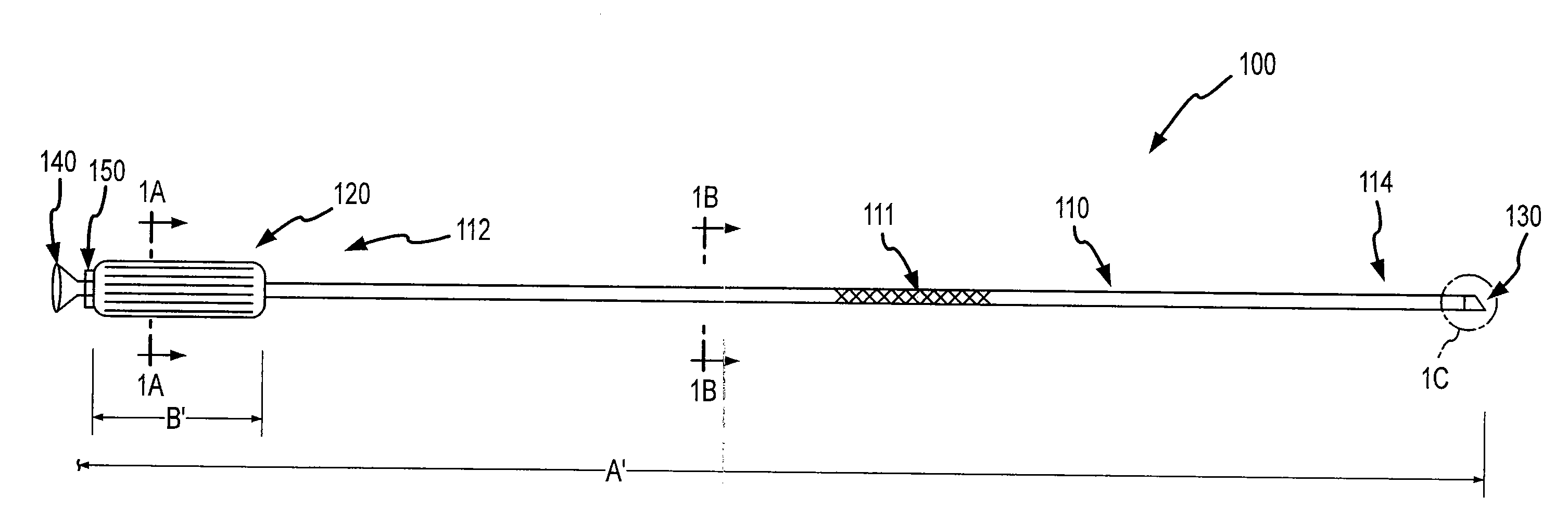
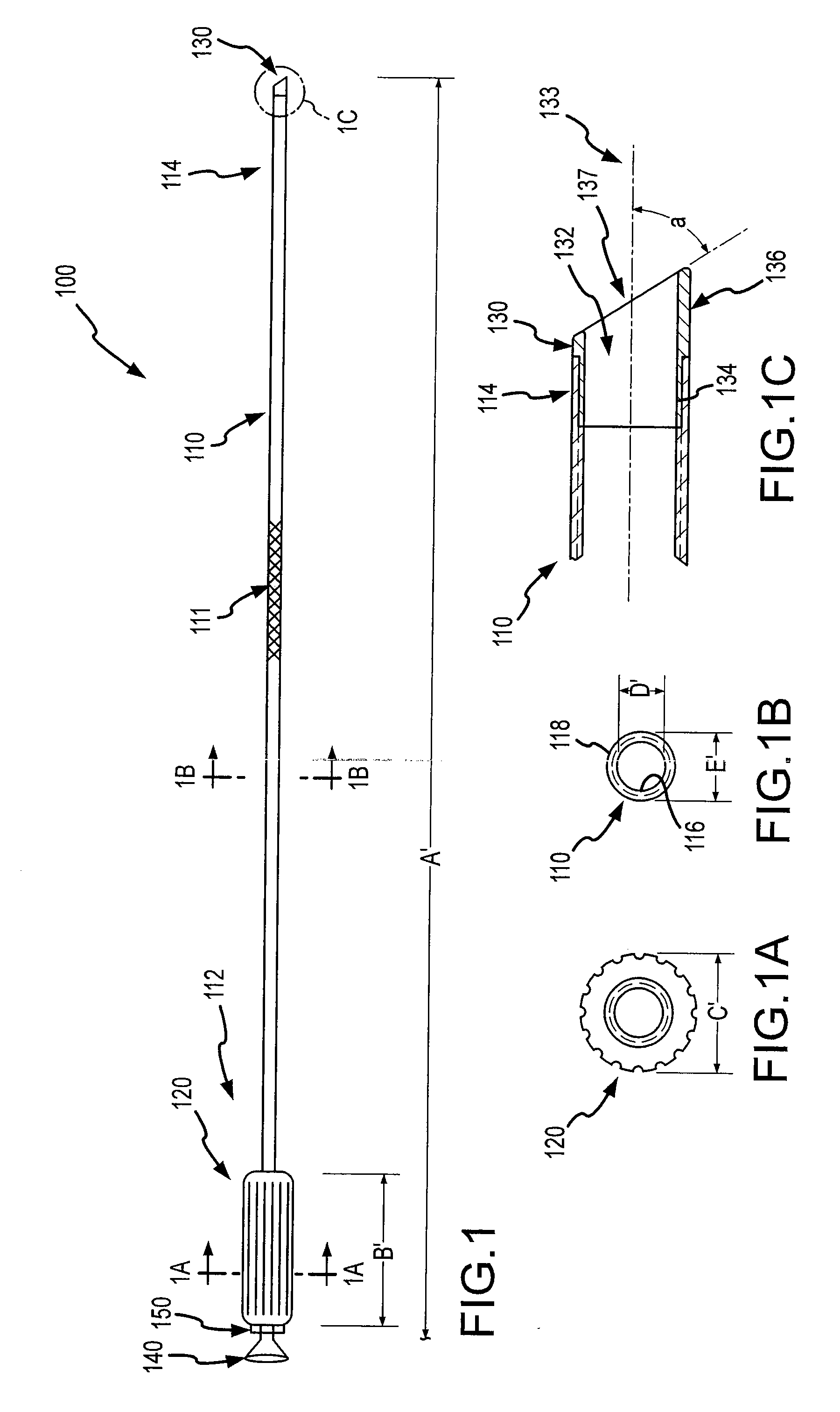
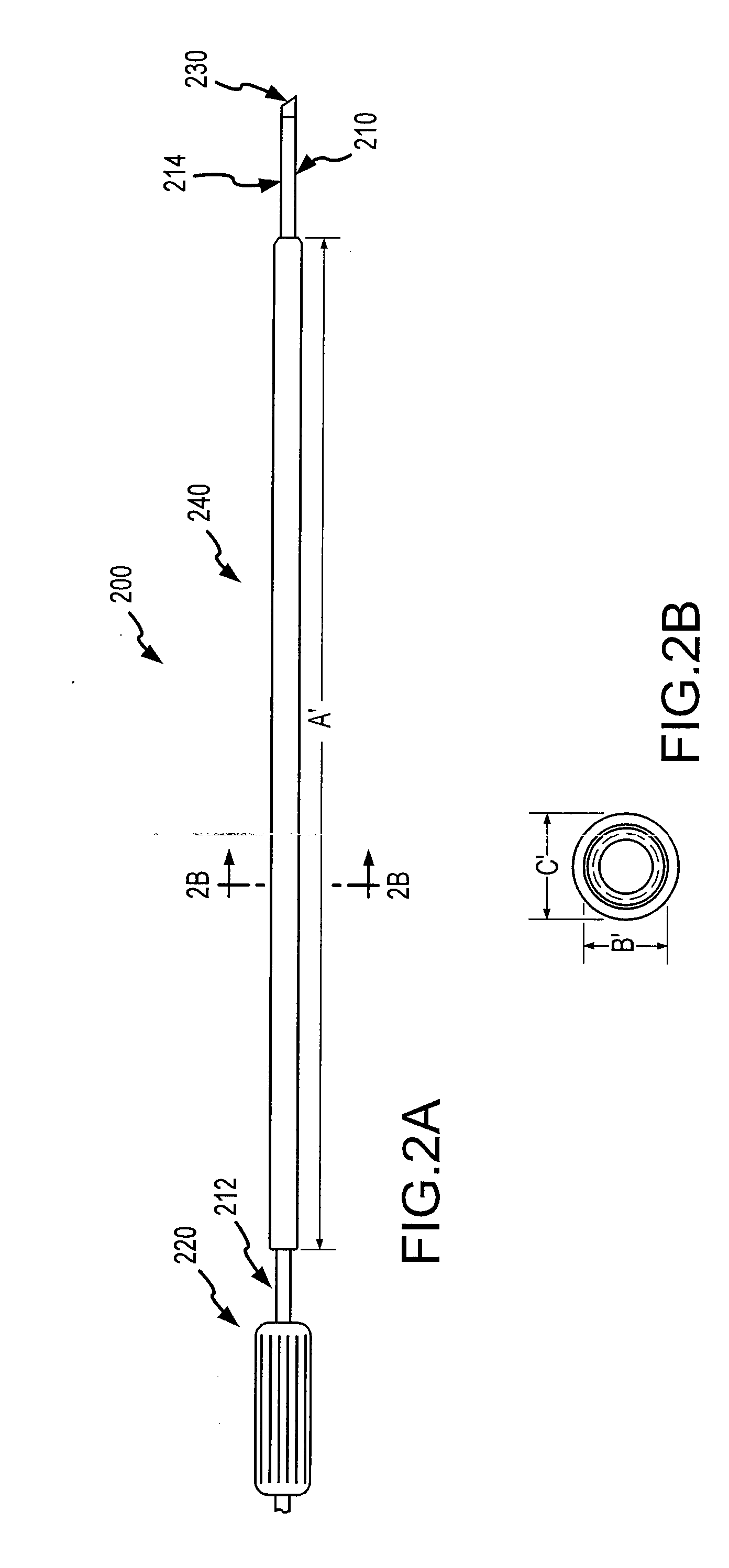
[0033]Embodiments of the present invention provide a mechanical sheath and cutting tip that can be safely deployed within the vascular system of a patient. Such systems includes a flexible and torqueable sheath and a hard separating mechanism. A separating system can include, for example, a flexible sheath coupled with a tip, which may include a separating surface or shape. The cutting or separating surface or shape can be contacted with patient tissue, and the sheath can be rotated to effect cutting or separating of the tissue. Although the sheath may be flexible, it can also be pushable in the sense that a force applied to the proximal end of the sheath is in large part transferred to the distal end of the sheath. The sheath may also exhibit a high resistance to kinking or crushing. For example, it is possible to force the sheath into a severe bend or tortuous path without causing permanent deformation or damage to the sheath. Moreover, the sheath maintains a desired amount of tor...


PUM


Abstract

Systems and methods for separating an object such as a pacing lead from a patient tissue involve a flexible and torqueable shaft having an internal lumen sized to receive the object, and a hard separating mechanism for separating the object from the tissue. Typically the shaft and separating mechanism are advanced along or toward the object, and the separating mechanism is contacted with the tissue. The shaft is rotated to effect separation between the object and the tissue. The systems and methods are well suited for use in cardiac pacing or defibrillator lead explant procedures.

Description

CROSS-REFERENCES TO RELATED APPLICATIONS[0001]This application is related to U.S. patent application Ser. No. ______, filed ______ (titled Retractable Separating Systems and Methods), the entire contents of which are incorporated herein by reference for all purposes.BACKGROUND OF THE INVENTION[0002]The present application relates generally to systems and methods for separating tissue in a patient, and more specifically, to techniques for separating pacing leads from a patient.[0003]Cardiac pacing systems typically include a pacemaker and a pacing lead, which are placed inside the body of a patient. The pacemaker includes a power source and circuitry configured to send timed electrical pulses to the pacing lead. The pacing lead carries the electrical pulse to the heart to initiate a heartbeat, and transmits information about the heart's electrical activity to the pacemaker. The pacing lead can include a fixation mechanism that holds the lead to the cardiac tissue. In some cases, a pa...

Claims


Application Information

Patent Timeline
Patent Type & Authority Applications(United States)
IPC IPC(8): A61B1/32
CPCA61B1/32A61B17/32002A61N2001/0578A61N1/057A61B2017/320056A61B17/3205A61B2017/320044
Inventor TAYLOR, KEVIN D.REISER, CHRISCOE, SEANHARLAN, KENNETH D.KENNERGREN, CHARLES
Owner SPECTRANETICS
Why Eureka
Try Eureka