Joint implant and a surgical method associated therewith

a surgical method and joint technology, applied in bone implants, medical science, prosthesis, etc., can solve the problems of increased loosening of such devices, biomechanical instability, and less use of techniques today, and achieve the effect of facilitating the passage of osteoinductive agents

Inactive Publication Date: 2008-06-26
DEPUY MOTION
View PDF99 Cites 116 Cited by
  • Summary
  • Abstract
  • Description
  • Claims
  • Application Information

AI Technical Summary

Benefits of technology

[0038]The implant may have any combination of holes or pores or gaps that permits bone to grow through the device and the easy passage of osteoinductive agents.

Problems solved by technology

Further, bone graft delivery, containment, ectopic bone formation—especially with liquid bone morphogenic protein like substances, and resorption of loose bone graft remain problems with inter-transverse process spinal fusion.
This technique is not as frequently used today and the triple joint complex (i.e., the intervertebral disc space and the two facet joints) being fused may be biomechanically destabilised because of a space created between the facet joint surfaces, or worse, by the subtotal resection of the entire bony facet joint complexes.
This technique leads to increased load sharing on any associated pedicle screw / rod construct and therefore may lead to increased loosening of such devices, and reduced fusion rates.
However, the hole created in the spinal facet joint and filled by the bone plug may not be stable enough after surgery.
The minimisation of the hole created by compression of the bone plug may cause nerve compression which is undesirable.
Pedicle screws and rods are therefore often required with this type of surgery and loosening of the screws in the pedicles in this setting would be undesirable and probable.
This can cause damage to the nerve root which is undesirable.
However, the facet joint fusion time is relatively high as there are a limited number of fenestrations that extend through the implants that promote fusion.
Further, many of the implants are solid which do not permit osteoinductive agents to be placed within the implants.

Method used


Image

  • Joint implant and a surgical method associated therewith
  • Joint implant and a surgical method associated therewith
  • Joint implant and a surgical method associated therewith

Examples


Embodiment Construction

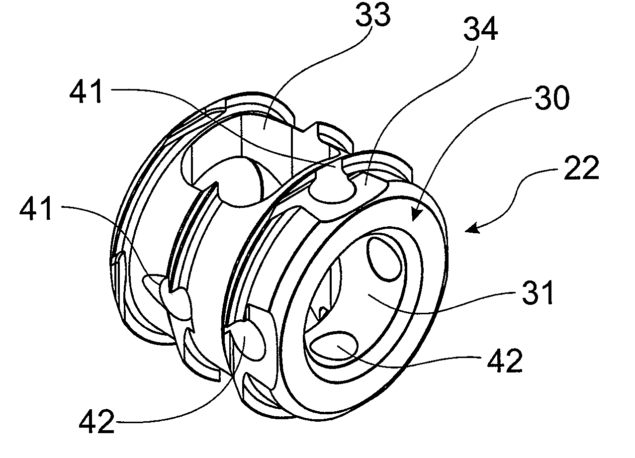
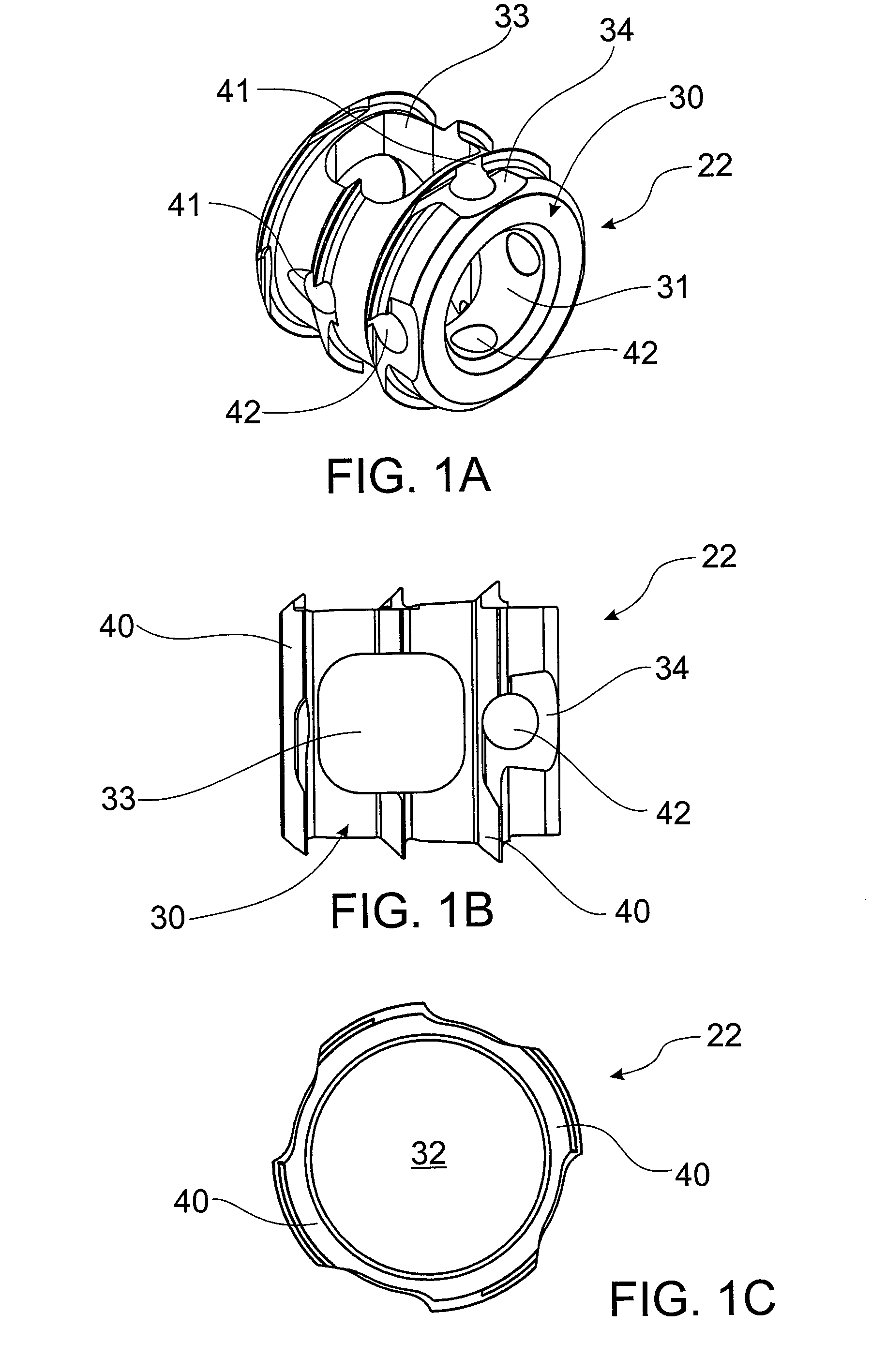
[0057]FIGS. 1A to 1C show an implant 22 able to be inserted into a surgically prepared spinal facet joint. It should be appreciated that even though this implant 22 has been specifically developed for use in surgically prepared spinal facet joints, it may have applications in other areas of the body such as the radio-carpal joint, acromio-clavicular joint, carpal joints, metacarpal joints, tarsal joints, or any other synovial or fibrous joint in the skeleton.

[0058]The implant 22 is made from titanium and may be coated with hydroxyapatite, or treated with a roughening technique such as acid / alkali treatments to promote a surface that enables bone on-growth. The implant 22 includes body 30 which is frusto conical in shape. That is, the body 30 is tapered from a top of the body 30 to a base of the body 30. A hollow central cavity 31 extends through a centre of the body 30 and an end wall 32 is located adjacent the end of the body 30. Large fenestrations 33 extend through the body 30. T...


PUM

PropertyMeasurementUnit
surface areaaaaaaaaaaa
driving forceaaaaaaaaaa
rotational forceaaaaaaaaaa

Abstract

A method of performing surgery to enable joint fusion by preparing bony surfaces of a joint to create an enlarged space between sides of the joint in which subchondral bone of the joint is exposed, inserting a hollow structural implant, having at least two large fenestrations which are located on substantially opposite sides of the implant into the enlarged space so that the implant contacts the subchondral bone and orientating the implant so that the large fenestrations are located adjacent the subchondral bone on respective sides of the joint.

Description

CROSS REFERENCE TO RELATED APPLICATIONS[0001]This application claims the benefit of U.S. Provisional Application Ser. No. 60 / 875,974, filed 20 Dec. 2006, and U.S. Provisional Application Ser. No. 60 / 909,056, filed 30 Mar. 2007.FIELD OF THE INVENTION[0002]This invention relates to a joint implant and a surgical technique associated therewith. In particular the invention relates to spinal facet joint fusion and therefore will be described in this context. However, it should be appreciated that the implant may be used for fusing other joints throughout the body such as the radio-carpal joint, acromio-clavicular joint, carpal joints, metacarpal joints, tarsal joints, or any other synovial or fibrous joint in the skeleton.BACKGROUND OF THE INVENTION[0003]Spinal fusion is a very common procedure performed via posterior surgical approaches for degenerative and deformity spinal pathologies. Spinal fusion can also address fusion of spinal levels adjacent to motion retaining devices / technique...

Claims


Application Information

Patent Timeline
Patent Type & Authority Applications(United States)
IPC IPC(8): A61F2/44A61B17/58
CPCA61F2/4405A61F2/446A61F2/4611A61F2002/2817A61F2002/2835A61F2310/00796A61F2002/4212A61F2002/4256A61F2002/4475A61F2310/00023A61F2002/30904A61F2002/30593
Inventor LABROM, ROBERT DAVID
Owner DEPUY MOTION
Why Eureka
Try Eureka