Access control system
- Summary
- Abstract
- Description
- Claims
- Application Information
AI Technical Summary
Benefits of technology
Problems solved by technology
Method used
Image

Examples
embodiment 1
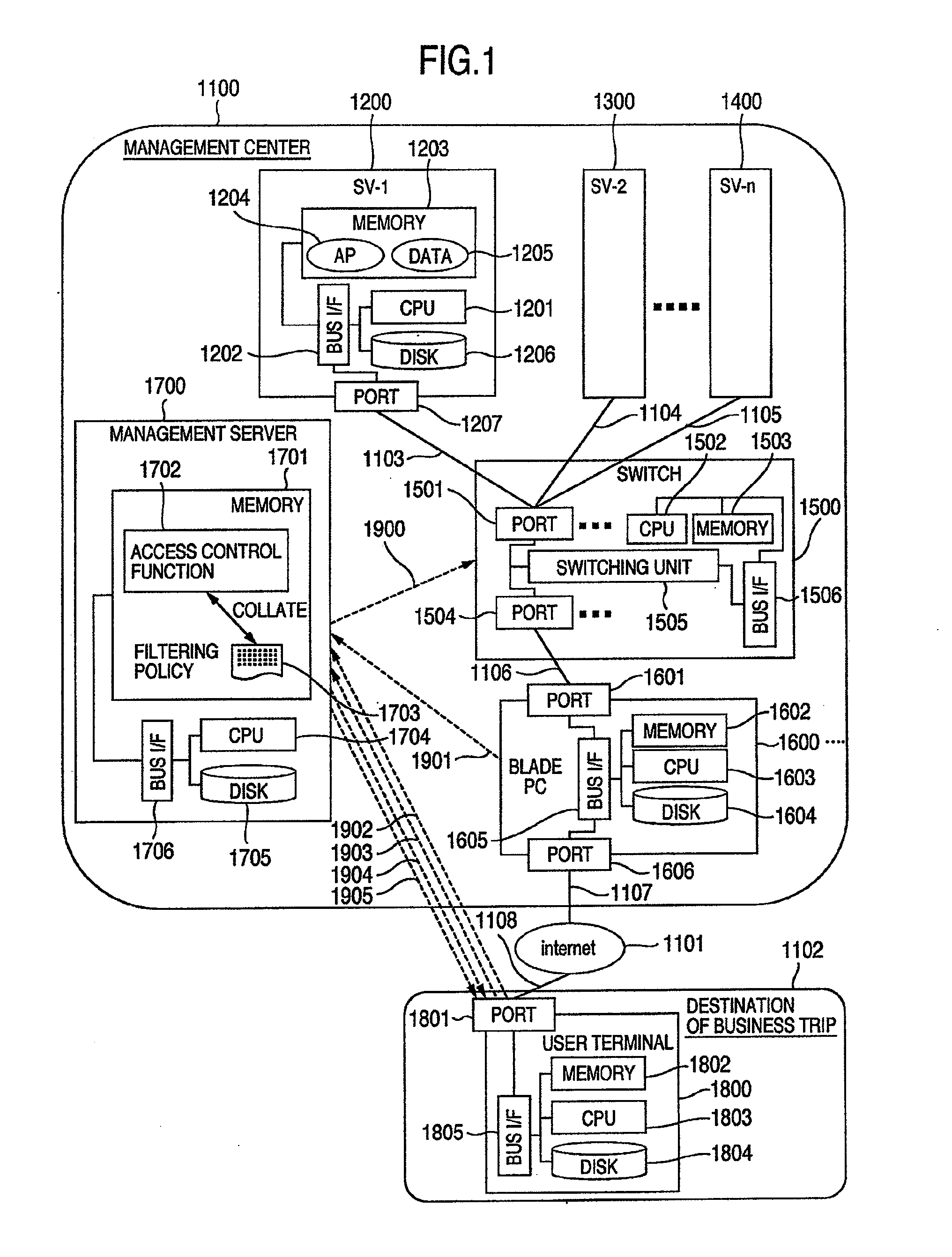
[0041]FIG. 1 is a constructional diagram of a thin client system as an example of a network system including an access control system according to the embodiment.
[0042]A thin client system 1100 has n servers 1200, 1300, and 1400 as resources. The n servers 1200 and the like are connected to blade PC 1600 (and blade PCs having the same configuration as the PC 1600) as examples of relay terminals through a switch 1500 as an example of a filtering apparatus. The blade PCs 1600 and the like are connected to an Internet 1101 as an example of a network. Although the network is conveniently assumed to be the Internet 1101 in consideration of a connection from a remote place in the embodiment, the network may be, for example, an Intranet, a network in a management center, or another arbitrary network.
[0043]The switch 1500 and a plurality of blade PCs 1600, and the like are connected to a management server 1700 as an example of a control server through a network (not shown). The management s...
embodiment 2
[0085]A network system according to the second embodiment will now be described.
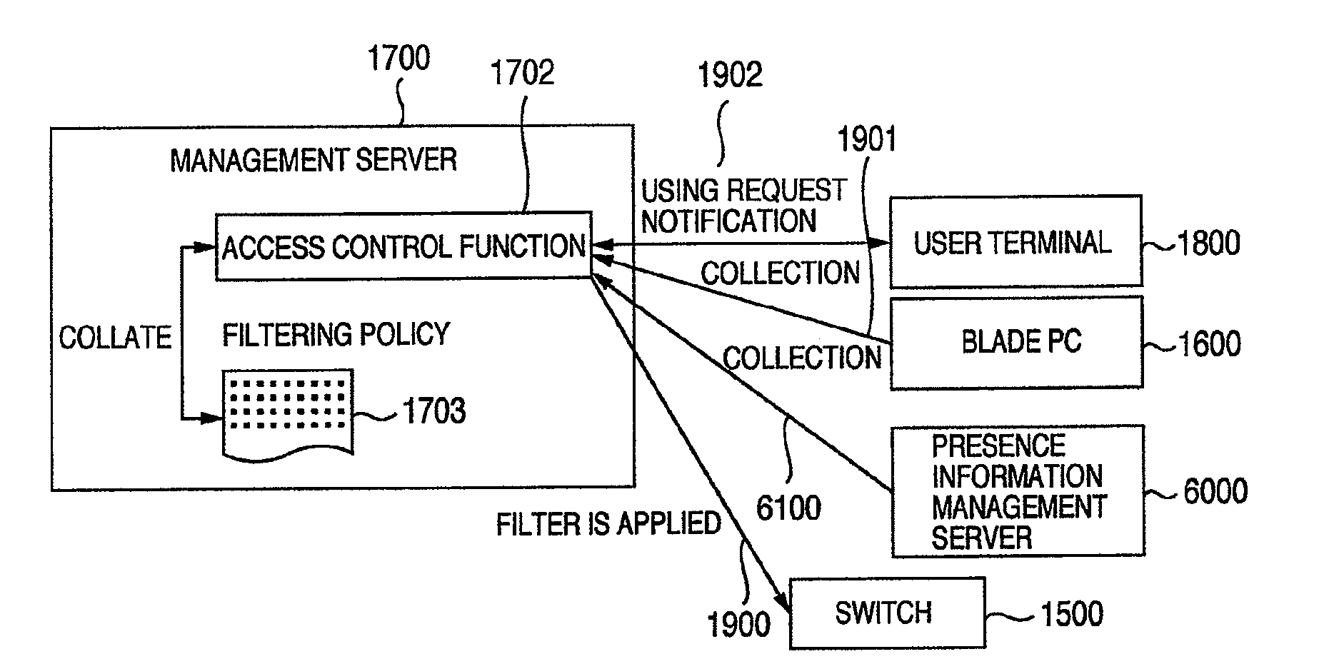
[0086]FIG. 6 is a diagram for explaining a schematic construction and the operation of the network system according to the embodiment. In the second embodiment, portions different from those in the first embodiment will be described.
[0087]According to the second embodiment, a situation information management server 6000 for managing the situation information of the user in a lump is newly provided in the network system according to the first embodiment, and further, the situation information is collected from the situation information management server 6000 instead of collecting the situation information from each user terminal 1800 and blade PC 1600 (refer to 6100).
[0088]The situation information management server 6000 stores and manages the situation information such as schedule information of the user, object of the business trip of the user, destination of the business trip of the user, access object...
embodiment 3
[0090]A network system according to the third embodiment will now be described.
[0091]FIG. 7 is a diagram for explaining a schematic construction and the operation of the network system according to the embodiment. In the third embodiment, portions different from those in the first embodiment will be described.
[0092]The network system according to the embodiment newly has the situation information management server 6000 in the network system according to the first embodiment. The situation information management server 6000 stores and manages the situation information such as schedule information of the user, object of the business trip of the user, destination of the business trip of the user, access object of the user, and the like other than the position information of the user terminal. The access control function PG 1702 of the management server 1700 according to the third embodiment is a program for executing such processes that when the using request notification 1902 is recei...
PUM
 Abstract
Description
Claims
Application Information
 - R&D
- Intellectual Property
- Life Sciences
- Materials
- Tech Scout
- Unparalleled Data Quality
- Higher Quality Content
- 60% Fewer Hallucinations
Browse by: Latest US Patents, China's latest patents, Technical Efficacy Thesaurus, Application Domain, Technology Topic, Popular Technical Reports.
© 2025 PatSnap. All rights reserved.Legal|Privacy policy|Modern Slavery Act Transparency Statement|Sitemap|About US| Contact US: help@patsnap.com