
Cooling ring for use in manufacturing of fiberglass wool

a cooling ring and fiberglass wool technology, applied in the field of fiberglass insulation, can solve the problems of increasing the raw material cost of insulation, undesirable evaporation of binder, and prone to evaporation or prying, so as to improve the cooling efficiency of the spray, improve the cooling effect of the veil, and reduce the amount of binder to be applied.

Inactive Publication Date: 2008-07-03
OWENS CORNING FIBERGLAS TECH INC
View PDF38 Cites 59 Cited by
  • Summary
  • Abstract
  • Description
  • Claims
  • Application Information

AI Technical Summary

Benefits of technology

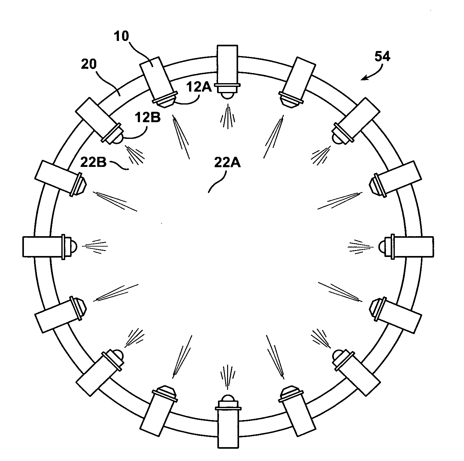
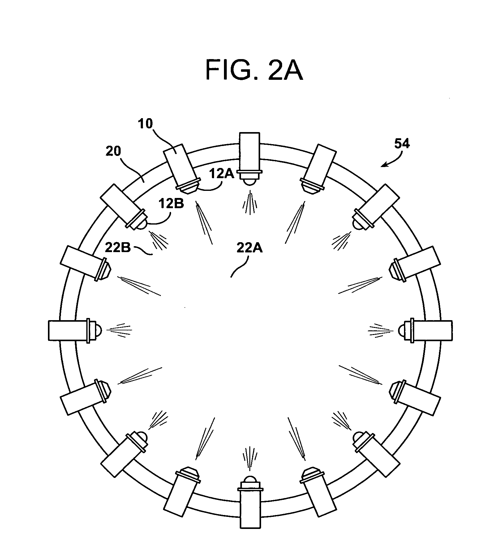
[0004]The present invention provides improved cooling of a veil of glass fibers by using a combination of nozzle assemblies. The nozzle assemblies include air caps of differing configurations to control the penetration of the spray into the veil. One suitable spray configuration is a nozzle assembly having a punch spray air cap that creates a high velocity flow of droplets to penetrate the veil to cool the fibers at the interior. Another suitable nozzle assembly configuration is a nozzle assembly having a flat air cap that creates a low velocity, dispersed spray pattern to cool the exterior of the veil. Preferably, the nozzle assembly having a flat air cap creates a very fine particle size to increase the cooling efficiency of the spray. By using the cooling ring of the present invention, lower levels of binder to be applied to the fibers and environmental emissions from the plant may be reduced.

Problems solved by technology

The binder is susceptible to evaporation or precuring when applied to glass fibers that are too hot.
Evaporation of the binder is undesirable because it increases the raw material cost of the insulation and may create undesirable environmental emissions.
Precuring of the binder is undesirable because it reduces the surface quality of the insulation and may reduce the R-value of the insulation.
The spray rings of the prior art cool did not have the ability to effectively cool the exterior of the veil of glass fibers while effectively cooling the fibers at the interior of the veil.
This resulted in warm fibers that may cause evaporation and precure of the binder.

Method used


Image

  • Cooling ring for use in manufacturing of fiberglass wool
  • Cooling ring for use in manufacturing of fiberglass wool
  • Cooling ring for use in manufacturing of fiberglass wool

Examples


Embodiment Construction

[0012]The present invention provides improved cooling of a veil of glass fibers by using a combination of nozzle assemblies. The nozzle assemblies include air caps of differing configurations to control the penetration of the spray into the veil. One suitable spray configuration is a punch spray air cap that creates a high velocity flow of droplets to penetrate the veil to cool the fibers at the interior. Another suitable configuration is a flat air cap that creates a low velocity, dispersed spray pattern to cool the exterior of the veil. Preferably, the flat air cap creates a very fine particle size to increase the cooling efficiency of the spray. By using the cooling ring of the present invention lower levels of binder to be applied to the fibers and environmental emissions from the plant may be reduced.

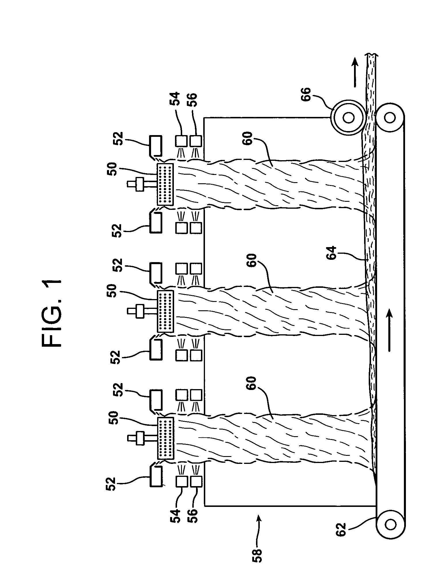
[0013]As shown in FIG. 1, a glass fiber manufacturing line including a fiber forming section 58. The forming section 58 includes a number of fiberizing spinners 50 that are supplie...


PUM

PropertyMeasurementUnit
Angleaaaaaaaaaa
Angleaaaaaaaaaa
Angleaaaaaaaaaa

Abstract

The present invention provides improved cooling of a veil of glass fibers by using a combination of nozzle assemblies. The nozzle assemblies include air caps of differing configurations to control the penetration of the spray into the veil. One suitable spray configuration is a nozzle assembly having punch air cap that creates a narrow exit angle, high velocity flow of droplets to penetrate the veil to cool the fibers at the interior. Another suitable configuration is a nozzle assembly having a flat air cap that creates a wide exit angle, low velocity, dispersed spray pattern to cool the exterior of the veil. Preferably, the flat air cap creates a very fine particle size to increase the cooling efficiency of the spray. By using the cooling ring of the present invention, lower levels of binder to be applied to the fibers and environmental emissions from the plant may be reduced.

Description

TECHNICAL FIELD AND INDUSTRIAL APPLICABILITY OF THE INVENTION[0001]The present invention relates to the manufacture of fibrous insulation, particularly fiberglass insulation. The present invention provides improved cooling of a veil of glass fibers during the manufacturing process. By using a combination of nozzle assemblies, the cooling ring of the present invention provides cooling of fibers on the interior of the veil as well as fibers on the exterior of the veil. The cooling ring of the present invention may also include nozzle assemblies that create very fine droplets that markedly reduce the heat within the veil. The cooler veil allows for lower levels of binder to be applied to the fibers and reduces environmental emissions.BACKGROUND OF THE INVENTION[0002]In the manufacture of fiberglass insulation molten glass is fiberized with a spinner to form a veil of glass fibers the fibers are cooled with a spray of water and then are coated with a liquid binder, such as a urea-formal...

Claims


Application Information

Patent Timeline
IPC IPC(8): C03B37/085
CPCC03C25/146
Inventor COOPER, WILLIAM R.BLACKWOOD, SCOTT J.LUCAS, MARC A.WARD, MICHAELBABBITT, WILLIAM M.RODENBAUGH, DAVID R.CROTHERS, STEVEN D.SHALLENBERGER, DAVIDLEWIS, MICHAEL P.FAUST, JOHN J.
Owner OWENS CORNING FIBERGLAS TECH INC
Learn More