Pulverized coal combustion boiler

a coal combustion and pulverized coal technology, applied in the direction of solid fuel combustion, combustion types, lighting and heating apparatus, etc., can solve the imbalance of the temperature of the vapor generated in the water wall pipe, the difference in the heat absorption balance between the front wall and the rear wall of the furnace, and the damage to the furnace wall surface. achieve the effect of enhancing the safety of the furnace wall surface, ensuring the combustion performance in a wide load range, and stable retention of the combustion flames

Inactive Publication Date: 2008-07-03
HITACHI LTD
View PDF12 Cites 9 Cited by
  • Summary
  • Abstract
  • Description
  • Claims
  • Application Information

AI Technical Summary

Benefits of technology

[0022]The arrangement of opposed burners at the water wall pipes of the furnace front wall and the furnace rear wall of the once-through boiler is excellent in ensuring the combustion performance in a wide load range because of the configuration that is advantageous for the stable retention of the combustion flames by the burners alone. However, because of the imbalance problem of the generated vapor temperatures, the application of the combustion method in which the opposed burners are arranged at the water wall pipes of the furnace front wall and the furnace rear wall of the furnace is difficult when the water walls of the once-through boiler furnace are formed with vertically arranged water wall pipes.
[0023]A first object of the present invention is to provide a pulverized coal combustion boiler for leveling heat loads of the plurality of water pipes constitute the furnace wall surfaces of the furnace in the entire load range to control the thermal stress generated in the furnace water pipes, enhancing safety of the furnace wall surfaces and extending life of the pulverized coal combustion boiler.
[0024]A second object of the present invention is to provide a pulverized coal combustion boiler having opposed burners placed at the water pipes vertically arranged on the furnace front wall and the furnace rear wall for making the heat loads in the furnace uniform to control an increase in the pipe wall temperatures of the water pipes of the furnace.

Problems solved by technology

This results in a substantial difference in the heat absorbing balance between the furnace front wall and the furnace rear wall.
As a result, the fluid temperature of water pipe outlets provided in the plurality of water pipe walls that constitute the furnace wall surfaces of the furnace front wall and the surface rear wall becomes imbalanced and the elongation of the water pipes are varied so that the thermal stress is generated on the furnace wall surfaces, which may damage the furnace wall surfaces.
This is reflected in the fluid temperature of the outlets of the water wall pipes of the furnace, causing imbalanced temperatures of the vapor generated in the water wall pipes.

Method used


Image

  • Pulverized coal combustion boiler
  • Pulverized coal combustion boiler
  • Pulverized coal combustion boiler

Examples


first embodiment

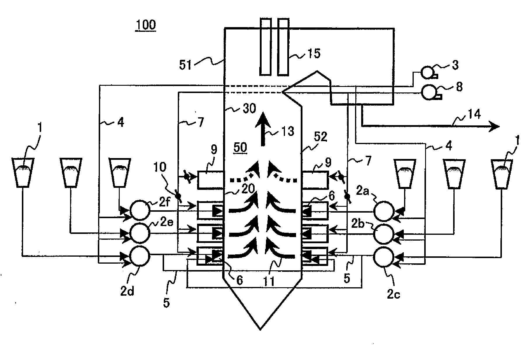
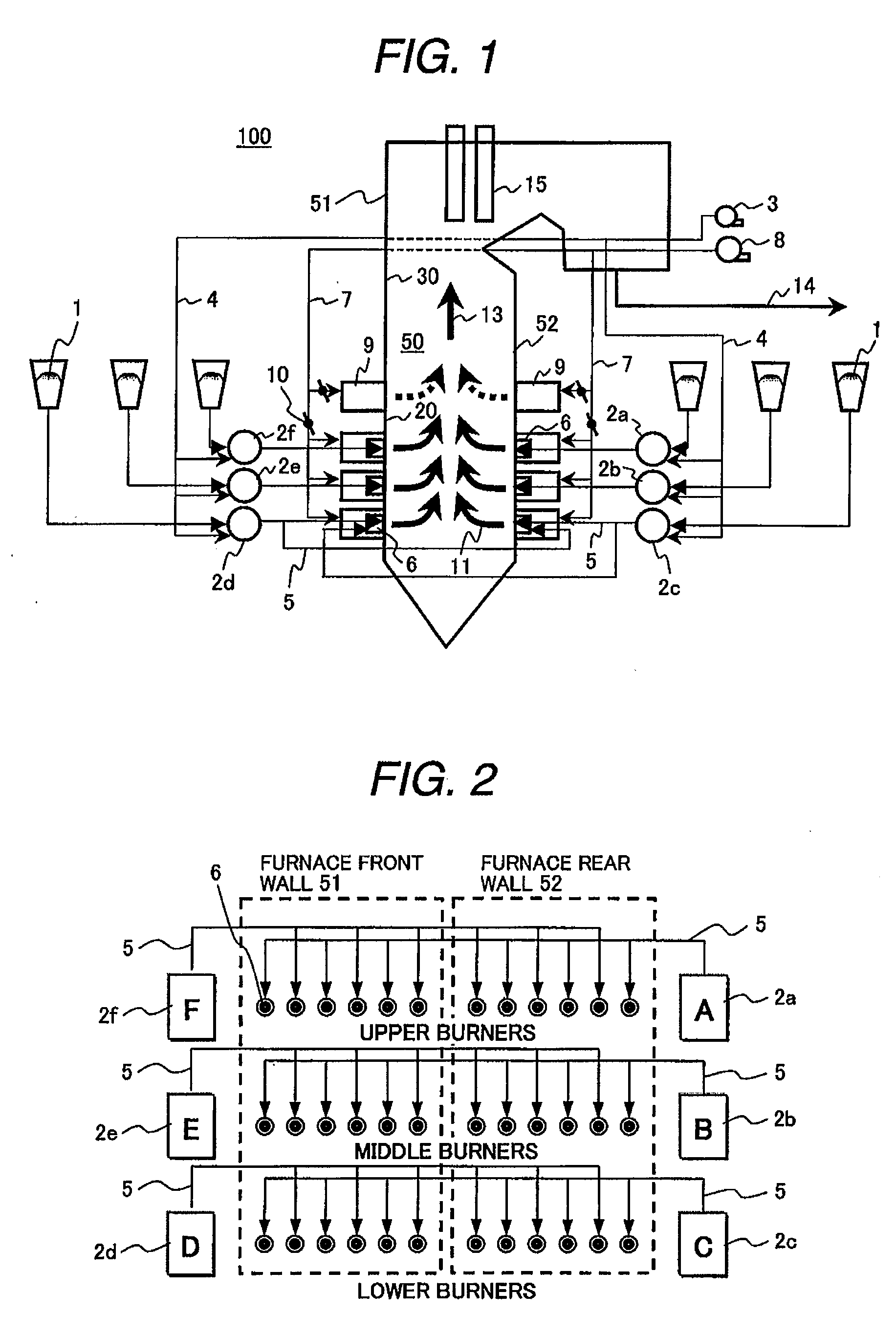
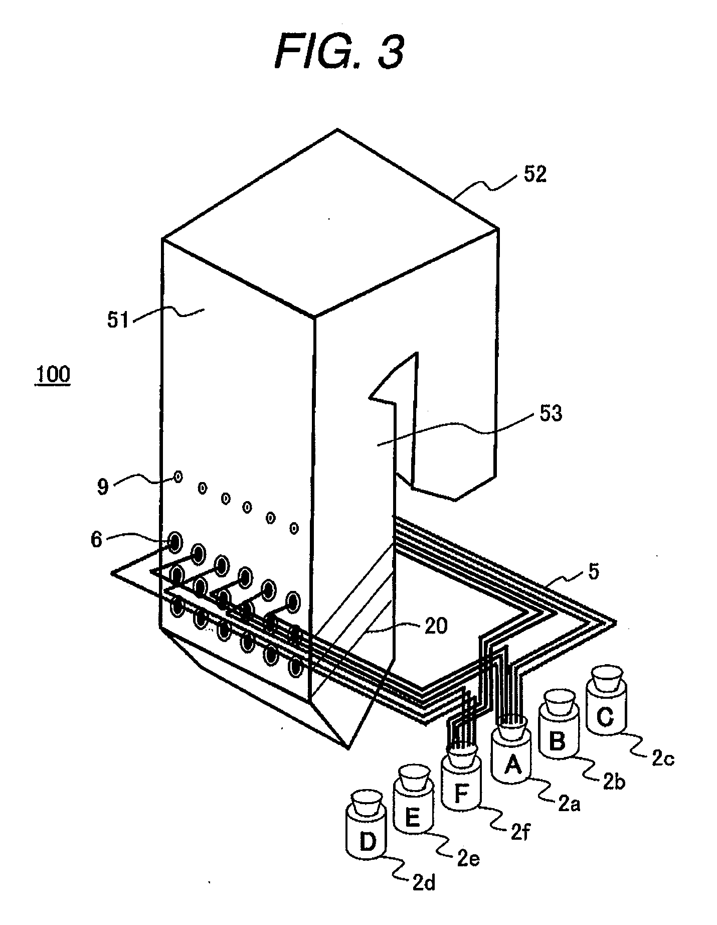
[0051]A pulverized coal combustion boiler 100 of a first embodiment of the present invention will be described with reference to FIG. 1 and FIG. 2. In FIG. 1, the pulverized coal combustion boiler 100 of the present embodiment comprises a furnace 50. Furnace wall surfaces that constitute the furnace 50 comprise a furnace front wall 51 constituting a wall surface of the furnace, a furnace rear wall 52 facing the furnace front wall 51, and a furnace sidewall 53 (shown in FIG. 3) serving as a sidewall between the furnace front wall 51 and the furnace rear wall 52. The furnace wall surfaces surround the furnace 50 so as to form a furnace combustion space in the furnace 50.

[0052]Water pipe walls 20 on which a multiplicity of water pipes are arranged in spirals are provided on the inner walls of the furnace wall surfaces that constitute the furnace 50. The water pipes of the multiplicity of the water pipe walls 20 absorb part of the combustion heat generated by burning the pulverized coal...

second embodiment

[0113]The pulverized coal combustion boiler of a second embodiment of the present invention will be described with reference to FIG. 8. The fundamental configuration of the pulverized coal combustion boiler of this embodiment is in common with that of the pulverized coal combustion boiler of the preceding embodiment shown in FIGS. 1 to 7. Therefore, the explanation of the configuration in common will be omitted, and only different configurations will be described.

[0114]As for each of the upper burner stage, the middle burner stage, and the lower burner stage on the furnace front wall 51 and the furnace rear wall 52 of the furnace wall surfaces of the furnace 50 in the pulverized coal combustion boiler of the present embodiment shown in FIG. 8, the height in the vertical direction of the burner stages on the furnace rear wall 52 is arranged to be higher than the height in the vertical direction of the burner stages of the furnace front wall 51.

[0115]Vertical shifting of the positions...

third embodiment

[0121]The pulverized coal combustion boiler of still a third embodiment of the present invention will be described with reference to FIG. 9. The fundamental configuration of the pulverized coal combustion boiler of this embodiment is in common with that of the pulverized coal combustion boiler of the preceding embodiment shown in FIGS. 1 to 7. Therefore, the explanation of the configuration in common will be omitted, and only different configurations will be described.

[0122]In the pulverized coal combustion boiler of the present embodiment shown in FIG. 9, the pulverized fuel pipes 5 for supplying the pulverized coal fuel to three burners 6a and three burners 6f arranged on the furnace front wall 51 and the furnace rear wall 52 from two mills (mill 2f and mill 2a) arranged on one side of the furnace sidewall 53 are connected to six burners 6 that are arranged on each of the furnace front wall 51 and the furnace rear wall 52 and that form the upper burner stage of the furnace wall su...


PUM


Abstract

A pulverized coal combustion boiler 100 comprising: a furnace 50; a plurality of burners 6 for supplying and burning pulverized coal fuel in the furnace arranged at positions of a plurality of stages having different heights on a furnace front wall 51 and a furnace rear wall 52 of furnace wall surfaces forming the furnace 50, the furnace rear wall 52 arranged for facing the furnace front wall 51; a plurality of mills 2 arranged for supplying the pulverized coal fuel to the plurality of burners 6 arranged at each of the plurality of stages; and pulverized fuel pipes 5 arranged for distributing and supplying the pulverized coal to the plurality of burners 6 at each of the stages of the furnace front wall 51 and the furnace rear wall 52 from each of the plurality of mills 2.

Description

CLAIM OF PRIORITY[0001]The present application claims priority from Japanese application serial No. 2006-342414, filed on Dec. 20, 2006, and Japanese application serial No. 2006-351536, filed on Dec. 27, 2006, the contents of which are hereby incorporated by reference into this application.BACKGROUND OF THE INVENTION[0002]1. Field of the Invention[0003]The present invention relates to a pulverized coal combustion boiler to burn pulverized coal.[0004]2. Description of Related Art[0005]In a conventional pulverized coal combustion boiler as shown in Japanese Application Patent Laid-Open Publication No. 2001-221406, one mill that produces and supplies pulverized coal is disposed on each of three burner stages (upper stage, middle stage, and lower stage) arranged on a furnace front wall and a furnace rear wall that constitute a furnace (six mill total).[0006]The feed rate of supplying coal to the boiler is reduced to lower the heat output in the furnace when the pulverized coal combustio...

Claims


Application Information

Patent Timeline
Patent Type & Authority Applications(United States)
IPC IPC(8): F23D1/00F23K3/00
CPCF23C6/047F23M5/08F23D1/00
Inventor ITO, OSAMUTANIGUCHI, MASAYUKIKOBAYASHI, HIRONOBUYAMAMOTO, KEIICHIROSHIMOGORI, YOSHIOOKAZAKI, TERUYUKIKIYAMA, KENJI
Owner HITACHI LTD
Why Eureka
Try Eureka