Illumination system including a curved mirror for an imaging-based bar code reader

a bar code reader and illumination system technology, applied in the field of illumination systems including curved mirrors, can solve the problems of high cost and inefficiency of secondary sources of light to illuminate bar codes, and the type of system is very inefficient, and achieves the effect of sufficient illumination level

Inactive Publication Date: 2008-07-03
SYMBOL TECH INC
View PDF4 Cites 7 Cited by
  • Summary
  • Abstract
  • Description
  • Claims
  • Application Information

AI Technical Summary

Benefits of technology

[0009]In the present invention a curved (preferably parabolic) illumination mirror is used to illuminate the barcode. Light from a source strikes the parabolic mirror and does not significantly diverge so it efficiently illuminates the bar code. The parabolic mirror may encompass a large area, and this makes it easier to capture the image of the illumination source reflected from the bar code by an imaging camera.
[0012]In one embodiment, a concave surface of the mirror approximates a section of a parabola and the source of light is located in a close proximity of the focal point. This arrangement produces nearly collimated light bouncing off from the mirror. The diverging angle of the outgoing light can be optimized in such a way to match the field of view of the imaging lens by this means providing sufficient illumination level over the entire FOV.

Problems solved by technology

These designs that use a secondary source of light to illuminate the barcode are both expensive and inefficient.
This type of system is very inefficient since the light gets scattered in all directions and only a small portion of light from the diffusive surface reaches the barcode.

Method used


Image

  • Illumination system including a curved mirror for an imaging-based bar code reader
  • Illumination system including a curved mirror for an imaging-based bar code reader
  • Illumination system including a curved mirror for an imaging-based bar code reader

Examples


Embodiment Construction

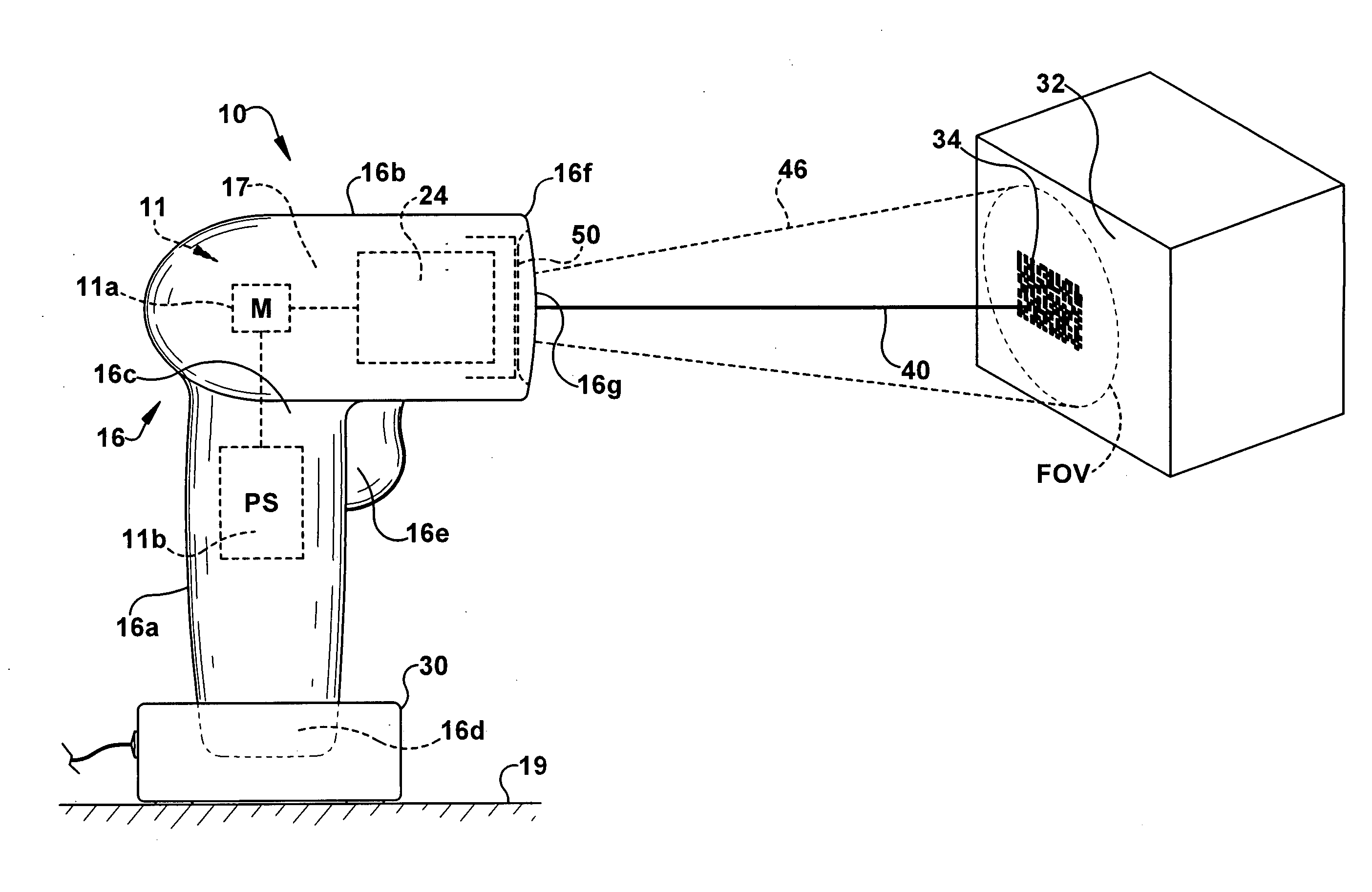
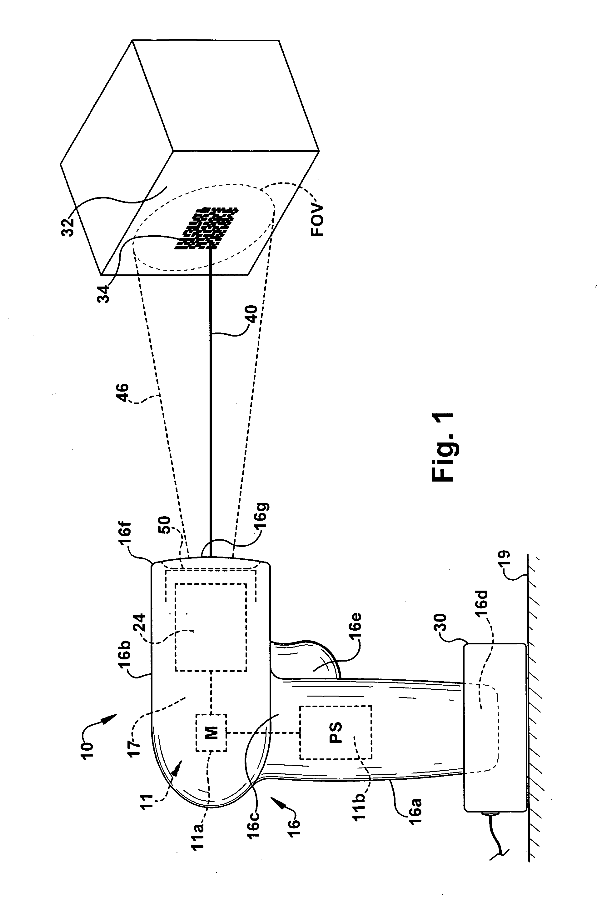
[0018]An exemplary embodiment of an imaging-based bar code reader of the present invention is shown schematically at 10 in the Figures. The bar code reader 10 includes a two dimensional (2D) imaging system 12 and a decoding system 14 supported in a housing 16. The imaging and decoding systems 12, 14 are capable of reading, that is, imaging and decoding both 1D and 2D bar codes and postal codes. The reader 10 is also capable of capturing images and signatures.

[0019]The decoding system 14 is adapted to decode encoded indicia within a selected captured image frame. The housing 16 supports reader circuitry 11 within an interior region 17 of the housing 16. The reader circuitry 11 includes a microprocessor 11a and a power supply 11b. The power supply 11b is electrically coupled to and provides power to the circuitry 11. The housing 16 also supports the imaging and decoding systems 12, 14 within the housing's interior region 17. The depicted reader 10 includes a docking station 30 adapted...


PUM


Abstract

A method and apparatus for illuminating a target object such as a bar code having areas of differing light reflectivity on the target. A bar code reader has a light source that is selectively activated and a reflecting mirror for reflecting light from the source from a housing to a target object within a field of view of an imaging capturing device. One suitable mirror is a parabolic mirror having a focal point approximately at the location of the light source.

Description

FIELD OF THE INVENTION[0001]The present invention relates to an illumination system for an imaging-based bar code reader and, more particularly, to an illumination system including a curved illumination mirror.BACKGROUND ART[0002]Various electro-optical systems have been developed for reading optical indicia, such as bar codes. A bar code is a coded pattern of graphical indicia comprised of a series of bars and spaces of varying widths, the bars and spaces having differing light reflecting characteristics. Some of the more popular bar code symbologies include: Uniform Product Code (UPC), typically used in retail stores sales; Code 39, primarily used in inventory tracking; and Postnet, which is used for encoding zip codes for U.S. mail. Systems that read and decode bar codes employing charged coupled device (CCD) or complementary metal oxide semiconductor (CMOS) based imaging systems are typically referred to hereinafter as imagining systems, imaging-based bar code readers or bar cod...

Claims


Application Information

Patent Timeline
Patent Type & Authority Applications(United States)
IPC IPC(8): G06K7/10
CPCG06K7/10732
Inventor VINOGRADOV, IGOR
Owner SYMBOL TECH INC
Why Eureka
Try Eureka