Scanning optical apparatus

a scanning optical apparatus and optical apparatus technology, applied in the field of scanning optical apparatus and multi-beam scanning optical apparatus, can solve the problems of difficult construction of compact scanning optical apparatus, long distance from the f lens to the surface to the scanned, and the thickness of the f lens, so as to achieve high-quality printing.

Inactive Publication Date: 2008-07-03
CANON KK
View PDF14 Cites 19 Cited by
  • Summary
  • Abstract
  • Description
  • Claims
  • Application Information

AI Technical Summary

Benefits of technology

[0018]It is a first object of the present invention to provide a compact scanning optical apparatus suitable for highly accurate printing in which when a beam of light from a light source converted by a collimator lens or the like is to be imaged on a surface to be scanned by an fθ lens through a light deflector, the lens shape (the main scanning plane shape) of the fθ lens in the main scanning plane thereof is optimized to thereby correct curvature of ...

Problems solved by technology

However, in the scanning optical apparatuses according to the prior art described above, according to Japanese Patent Publication No. 61-48684, curvature of image field in the sub scanning direction remains and a parallel beam of light is imaged on the surface to be scanned, and this has led to the problem that the distance from the fθ lens to the surface to the scanned becomes a focal length f and is long and it is difficult to construct a compact scanning optical apparatus.
In Japanese Laid-Open Patent Application No. 63-157122, the thickness of the fθ lens is great, and this has led to the problem that manufacture by molding is difficult and this makes a factor of increased cost.
Japanese Laid-Open Patent Application No. 4-104213 has suffered from the problem that distortion remains.
In Japanese Laid-Open Patent Application No. 4-50908, an fθ lens having a high-order aspherical surface is used and aberrations are corrected well, but there has been the problem that jitter of a period corresponding to the number of polygon surfaces occurs ...

Method used


Image

  • Scanning optical apparatus
  • Scanning optical apparatus
  • Scanning optical apparatus

Examples


embodiment 1

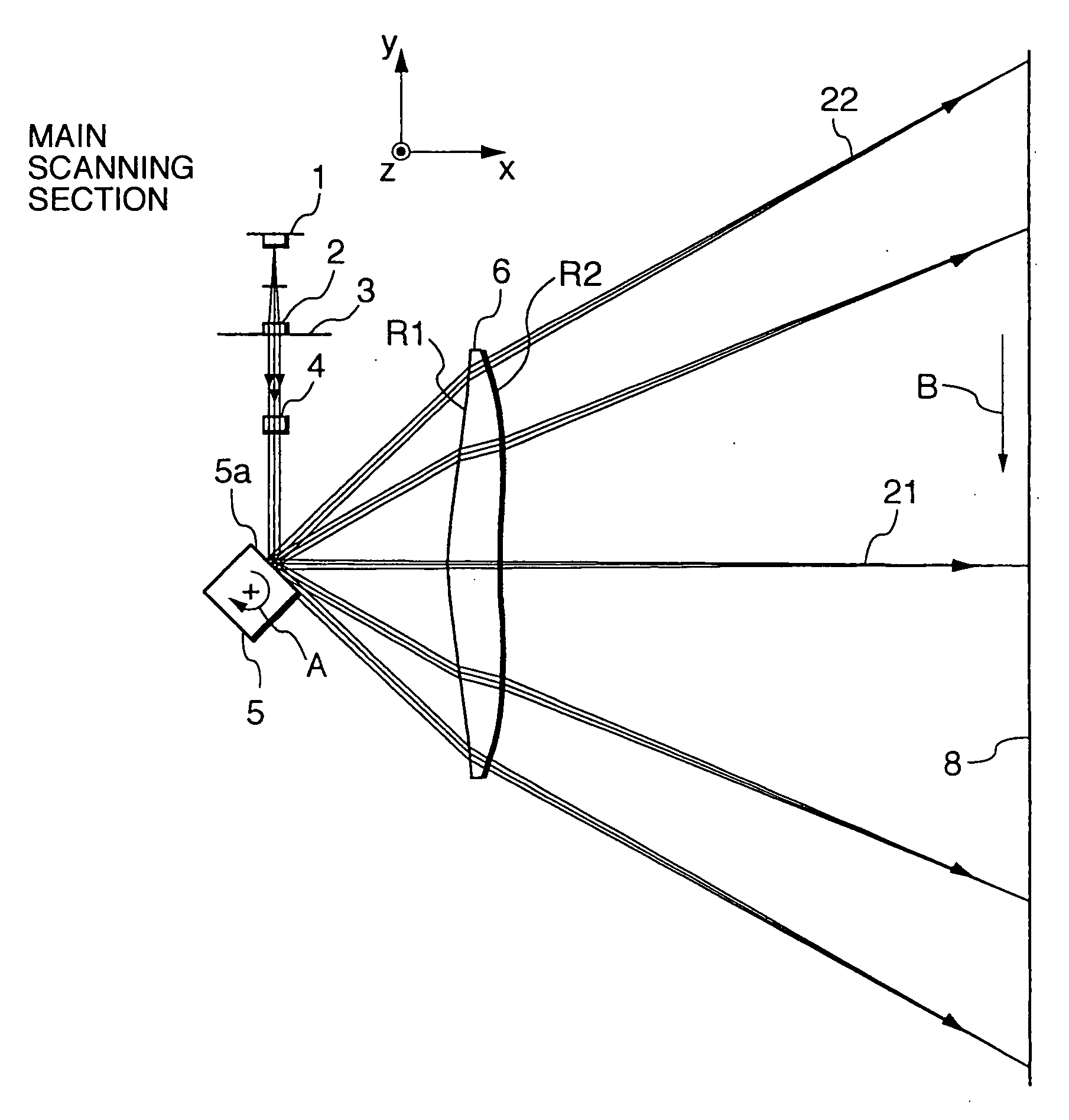
[0097]FIGS. 4A and 4B are cross-sectional views of Embodiment 1 of the present invention in the main scanning direction and the sub scanning direction, respectively.

[0098]In these figures, reference numeral 1 designates light source means (a light source unit) comprising, for example, a semiconductor laser.

[0099]Reference numeral 2 denotes a collimator lens as a first optical element which converts a divergent beam of light emitted from the light source means 1 into a convergent beam of light. Reference numeral 3 designates an aperture stop which regularizes the diameter of the beam of light passing therethrough.

[0100]Reference numeral 4 denotes a cylindrical lens as a second optical element which has predetermined refractive power only in the sub scanning direction and causes the beam of light passed through the aperture stop 3 to be imaged as a substantially linear image on the deflecting surface 5a of a light deflector (deflecting element) 5 which will be described later in the s...

embodiment 2

[0112]FIGS. 8A and 8B are cross-sectional views of Embodiment 2 of the present invention in the main scanning direction and the sub scanning direction, respectively. In FIGS. 8A and 8B, the same elements as the elements shown in FIGS. 4A and 4B are given the same reference numerals.

[0113]The differences of Embodiment 2 from the aforedescribed Embodiment 1 are that the divergent beam of light emitted from the semiconductor laser (the light source unit) is converted not into a convergent beam of light but into a parallel beam of light by the collimator lens and that corresponding thereto, the lens shape of the fθ lens is made different. In the other points, the construction and optical action of Embodiment 2 are substantially similar to those of Embodiment 1, whereby a similar effect is obtained.

[0114]Table 2 below shows the optical arrangement in Embodiment 2 and the aspherical surface coefficients of an fθ lens 26.

TABLE 2(Embodiment 2)wavelength usedλ(nm)780refractive index of fθ le...

embodiment 3

[0119]FIGS. 12A and 12B are cross-sectional views of Embodiment 3 of the present invention in the main scanning direction and the sub scanning direction, respectively. In these figures, the same element as the elements shown in FIG. 4 are given the same reference numerals.

[0120]The differences of Embodiment 3 from the aforedescribed Embodiment 1 are that the apparatus is comprised of a multibeam scanning optical system for scanning a plurality of beams of light emitted from light source means 11 having a plurality of (in Embodiment 3, too) light source units capable of being independently modulated, at a time, so as to have a predetermined interval therebetween on the surface to be scanned, and that correspondingly thereto, the lens shape of the fθ lens in the meridian-line direction (the sub scanning direction) is made different. In the other points, the construction and optical action of Embodiment 3 are substantially similar to those of the aforedescribed Embodiment 1, whereby a ...


PUM


Abstract

A scanning optical apparatus includes a light source, a deflecting element for deflecting a beam of light emitted from the light source, an optical device for causing the beam of light emitted from the light source to be imaged into a linear shape long in the main scanning direction on the deflecting surface of the deflecting element. The optical device is comprised of a first optical element and a second optical element, and a third optical element for causing the beam of light deflected by the deflecting element to be imaged into a spot-like shape on a surface to be scanned. The third optical element includes a single lens, the opposite lens surfaces of which both include a toric surface of an aspherical surface shape in the main scanning plane, the curvatures of the opposite lens surfaces in the sub scanning plane being continuously varied from the on-axis toward the off-axis in the effective portion of the lens.

Description

BACKGROUND OF THE INVENTION[0001]1. Field of the Invention[0002]This invention relates to a scanning optical apparatus and a multibeam scanning optical apparatus, and particularly to a scanning optical apparatus and a multibeam scanning optical apparatus suitable for use, for example, in an apparatus such as a laser beam printer (LBP) or a digital copying apparatus having the electrophotographic process adapted to deflect and reflect a beam of light optically modulated and emitted from light source means by a light deflector (deflecting element) comprising a rotatable polygon mirror or the like, thereafter optically scan a surface to be scanned through an imaging optical system having the fθ characteristic (fθ lens) and record image information.[0003]2. Related Background Art[0004]Heretofore, in the scanning optically apparatus of a laser beam printer or the like, a beam of light optically modulated and emerging from light source means in conformity with an image signal has been per...

Claims


Application Information

Patent Timeline
IPC IPC(8): B41J2/47
CPCB41J2/473G02B26/125G02B26/123G02B13/0005
Inventor KATO, MANABU
Owner CANON KK
Why Eureka
Try Eureka