Solid-state imaging device, camera, vehicle and surveillance device

Inactive Publication Date: 2008-07-03
PANASONIC CORP
View PDF9 Cites 20 Cited by
  • Summary
  • Abstract
  • Description
  • Claims
  • Application Information

AI Technical Summary

Benefits of technology

[0012]However, it is expected that calculation can be performed with high accuracy and efficiency in stereographic capturing by stereo cameras and so on, or for cameras which out

Problems solved by technology

Thus, there is the problem that the transmission speed of the video signal is not adequate.
Furthe

Method used


Image

  • Solid-state imaging device, camera, vehicle and surveillance device
  • Solid-state imaging device, camera, vehicle and surveillance device
  • Solid-state imaging device, camera, vehicle and surveillance device

Examples


Example

First Embodiment

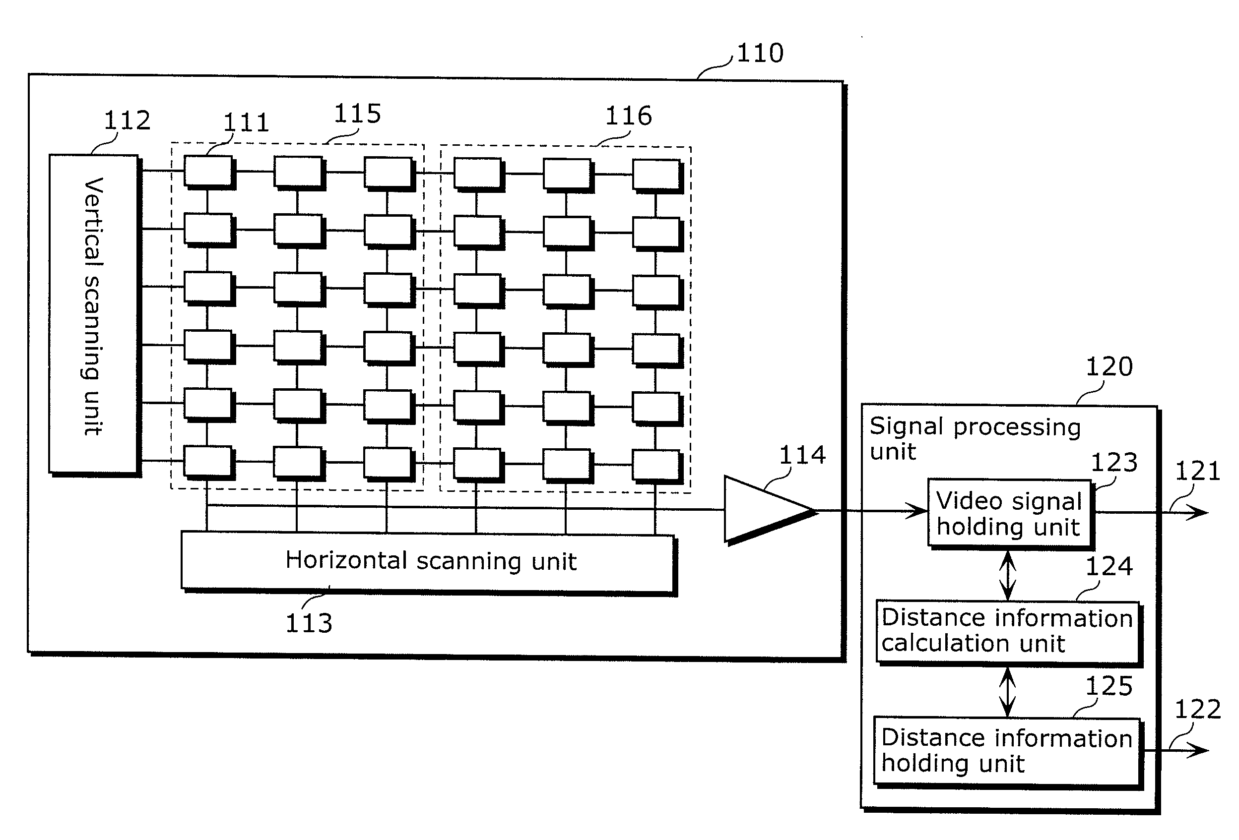
[0080]An imaging unit and a signal processing unit which calculates distance information to an object from the two image signals captured by the imaging unit are formed on the same semiconductor substrate in the solid-state imaging device according to the first embodiment of the present invention. Thus, a solid-state imaging device can be realized with a high resistance to noise which can calculate distance information with high accuracy and efficiency.

[0081]First, the structure of the solid-state imaging device according to the present embodiment is described.

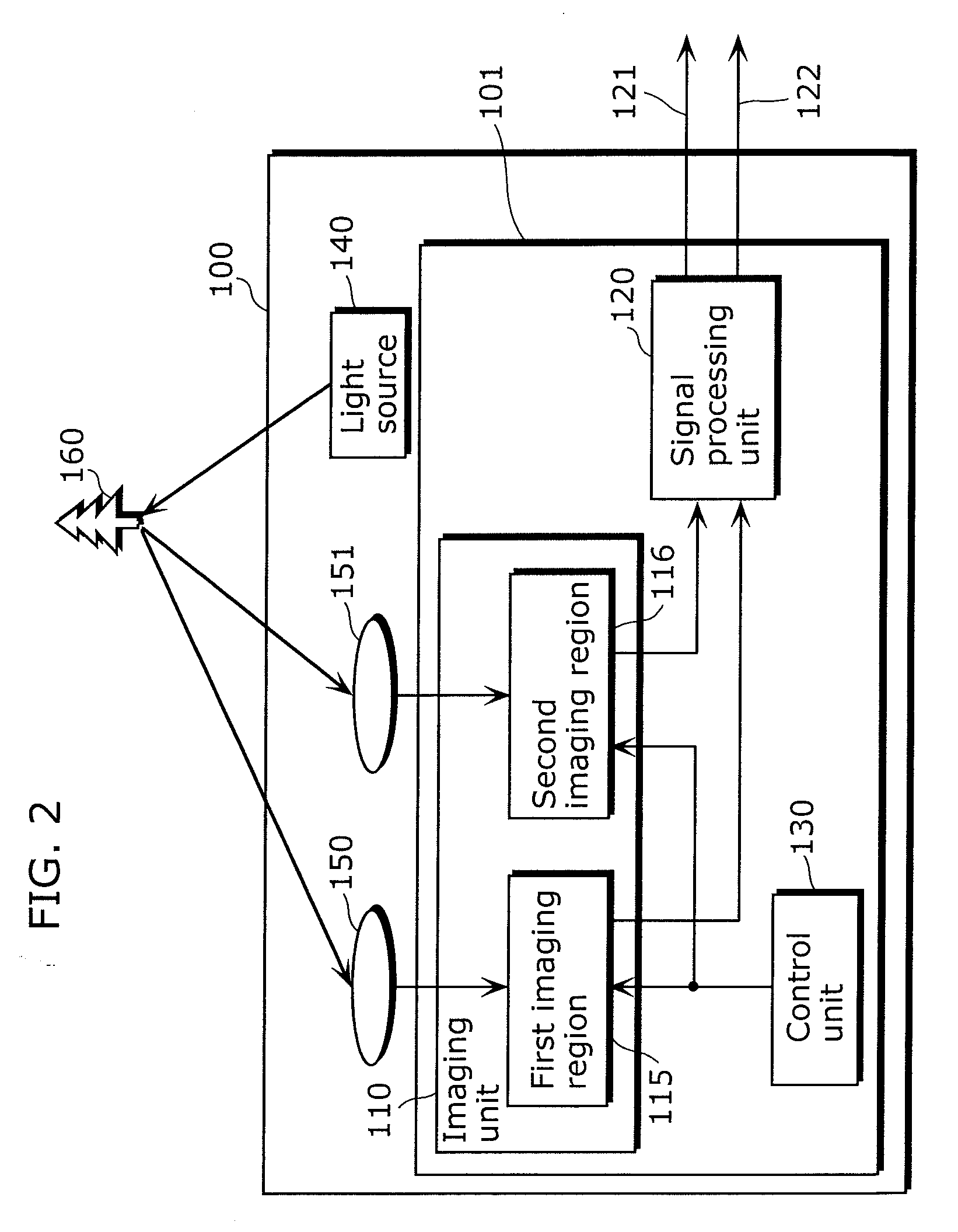
[0082]FIG. 2 is a diagram which shows the structure of the solid-state imaging device according to the first embodiment of the present invention.

[0083]The solid-state imaging device 100 according to FIG. 2 outputs video information and distance information related to a captured object 160. The solid-state imaging device 100 is, for example, a camera which includes a night vision function that uses light in a ne...

Example

Second Embodiment

[0148]The solid-state imaging device 100 according to the first embodiment described above controls light introduced into the first imaging regions 115 and the second imaging region 116 by using the filters 152 through 155 which allow light of different wavelengths to pass. However, since the wavelengths of light introduced into the first imaging region 115 and the second imaging region 116 differ, a difference in the image of the outputted video signal is generated.

[0149]The solid-state imaging device according to the second embodiment of the present invention further includes an imaging region for performing correction in addition to the two imaging regions. With this, the difference between the images outputted by the two imaging regions can be reduced by correcting the captured video signal.

[0150]Below, the structure of the solid-state imaging device according to the second embodiment of the present invention is described.

[0151]FIG. 16 is a diagram which shows a...


PUM


Abstract

The solid-state imaging device according to the present invention includes: an imaging unit which includes photoelectric conversion elements arranged in a matrix in a region having a first imaging region and a second imaging region; a first light introduction unit which guides and introduces light into the first imaging region; a second light introduction unit provided apart from the first light introduction unit and which guide and introduces light into the second imaging region; an output unit which: converts signal charge, which the photoelectric conversion elements arranged in the first imaging region have photoelectrically converted, into voltage or current and outputs the converted voltage or current as a first video signal; and converts signal charge, which the photoelectric conversion elements arranged in the second imaging region have photoelectrically converted, into voltage or current, and outputs the converted voltage or current as a second video signal; and a calculation unit which calculates information related to distance to an object using the first video signal and the second video signal outputted by the output unit; wherein the imaging unit, the output unit and the calculation unit are formed on the same semiconductor substrate.

Description

BACKGROUND OF THE INVENTION[0001](1) Field of the Invention[0002]The present invention relates to a solid-state imaging device, a camera, a vehicle and a surveillance device, especially to a solid-state imaging device which captures light introduced via independent optical incidence paths and outputs a video signal.[0003](2) Description of the Related Art[0004]A camera with two imaging regions is used in order to acquire image information according to a stereoscopic image or information related to the distance to the object (below, distance information). Cameras which output video information according to distance information detect the size and distance of an obstacle ahead using an on-board camera and can issue a warning to a driver. Further, collision with an obstacle can be avoided by automatically controlling the engine, brakes and steering wheel according to the detection of obstacles. Further, by installing a camera in the car, the size of the passenger (adult, child and so o...

Claims


Application Information

Patent Timeline
IPC IPC(8): H04N7/18H04N5/335G01C3/06H04N5/225H04N5/345H04N5/376H04N5/378H04N13/02
CPCG01S11/12G06T7/0077H04N13/0257G06T2207/10021H04N13/0217G06T2207/10012G06T7/596H04N13/257H04N13/218
Inventor TAKEDA, KATSUMI
Owner PANASONIC CORP
Why Eureka
Try Eureka