
Spur removal in pilot-tone OPM

a technology of pilot tone and opm, which is applied in the field of optical telecommunications, can solve problems such as the inadvertent removal of a normal part of the signal, and achieve the effect of improving accuracy and/or efficiency

Active Publication Date: 2019-07-09
HUAWEI TECH CO LTD
View PDF26 Cites 0 Cited by
  • Summary
  • Abstract
  • Description
  • Claims
  • Application Information

AI Technical Summary

Benefits of technology

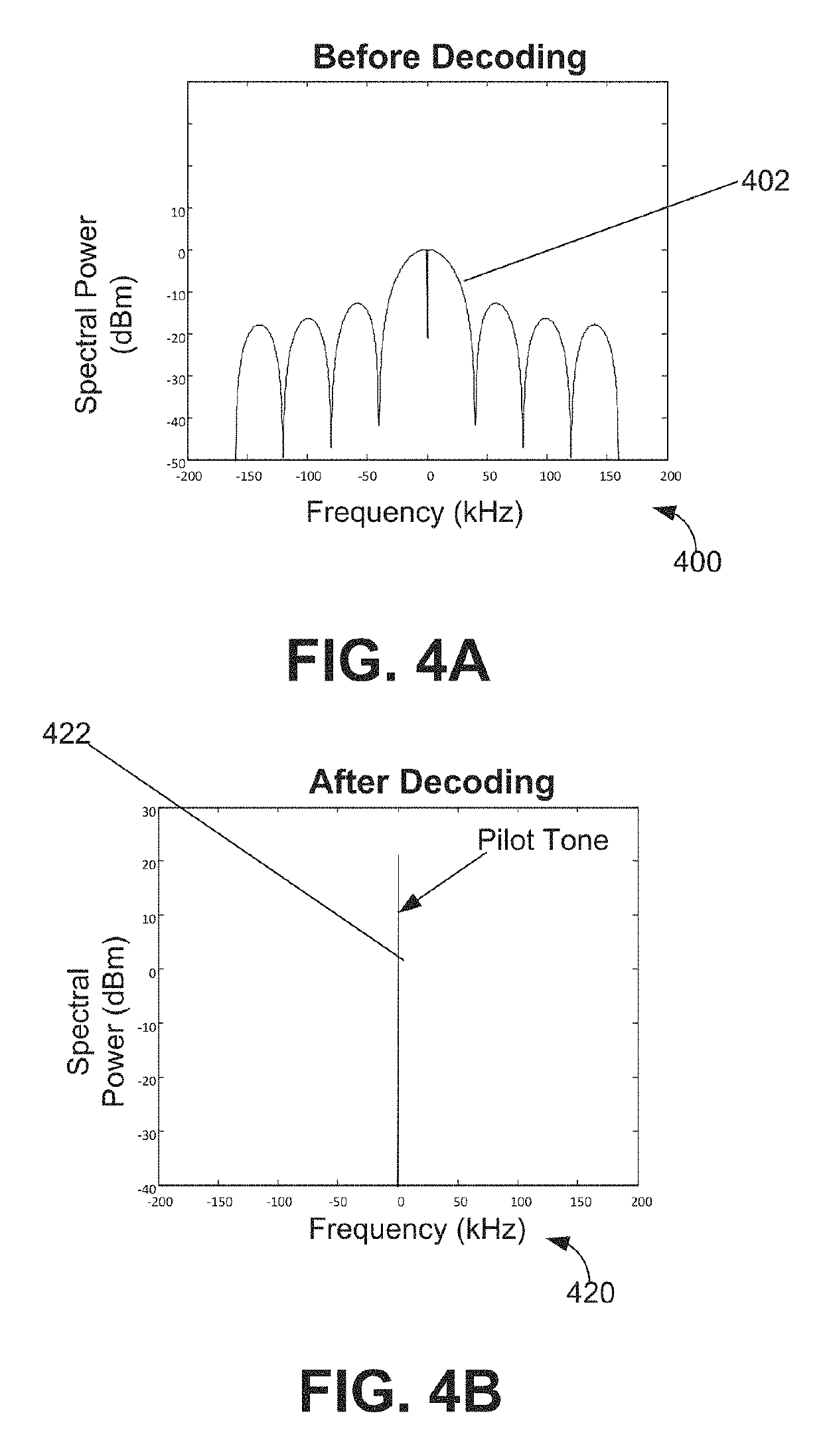
[0003]In various embodiments, an optical receiver configured to remove spectral spurs in a pilot-tone spread signal is provided. As used herein, a pilot-tone spread signal may be referred to as an expanded-spectrum pilot tone that is modulated onto a data-carrying signal when transmitted. Such a signal can contain spectral spurs that may interfere with the pilot tone. In those embodiments, the optical receiver may comprise a spurs removal component configured to remove the spectral spurs in the pilot-tone spread signal in a frequency domain before the pilot-tone is decoded. The removal of the spectral spurs in the pilot-tone spread signal may result in higher accuracy and / or efficiency in decoding the pilot tone.

Problems solved by technology

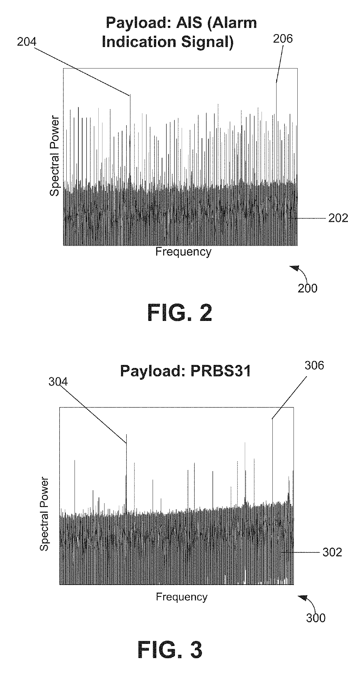
Such a signal can contain spectral spurs that may interfere with the pilot tone.
In some situations, the removal of the spectral spurs in the pilot-tone spread signal may result in inadvertent removal of a normal part of the signal.

Method used


Image

  • Spur removal in pilot-tone OPM
  • Spur removal in pilot-tone OPM
  • Spur removal in pilot-tone OPM

Examples


Embodiment Construction

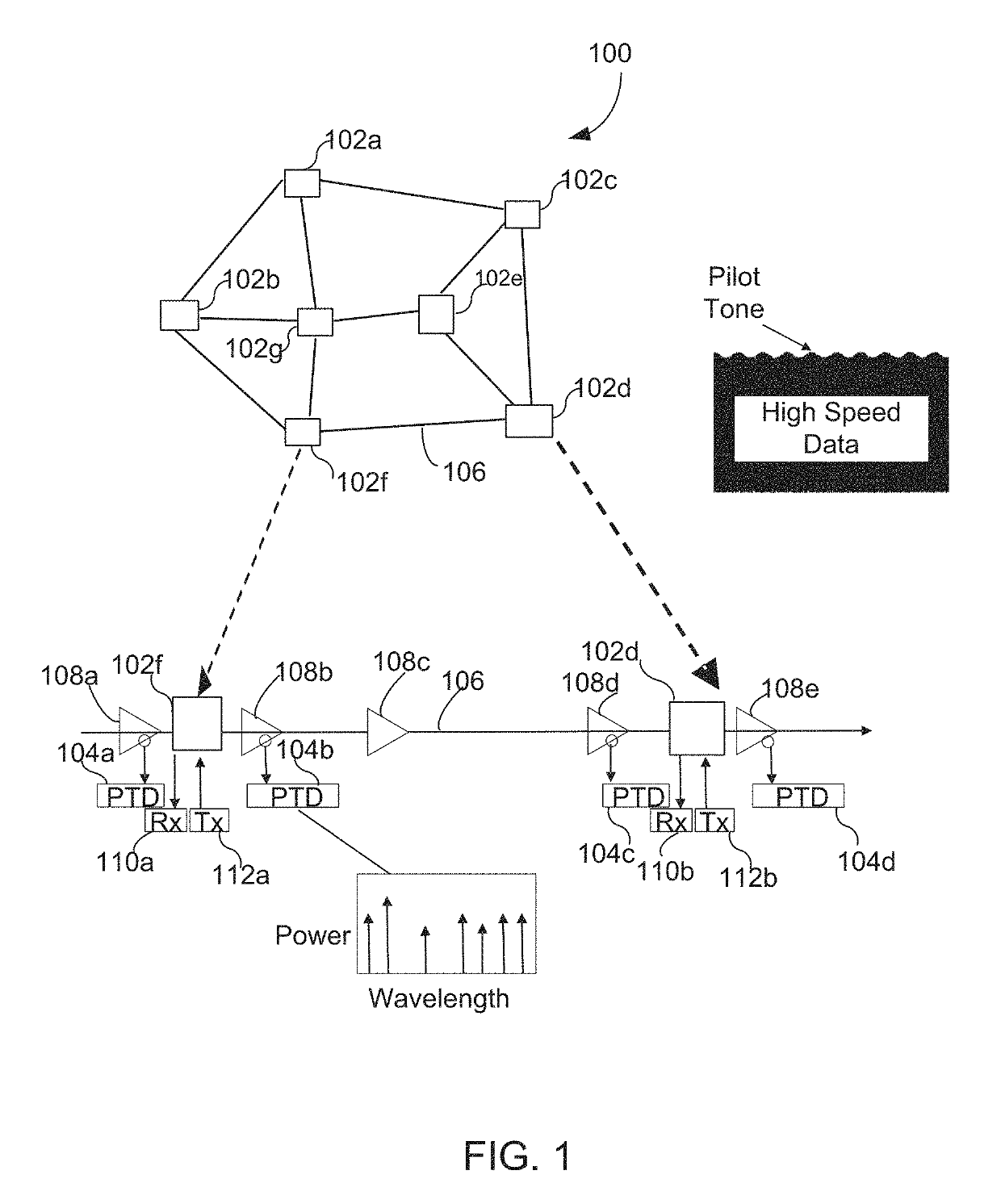
[0021]An optical network connects computers (or any other device which can generate or store data in electronic form) using optical fibers. To facilitate data communication, an optical network can include optical devices to generate optical (electrical) signals from electrical (respectively optical) data, to restore optical signals after they propagate through fibers, and to route optical signals through the network. Dense Wavelength Division Multiplexing (DWDM) is a fiber-optic transmission technique. It typically involves a process of multiplexing many different wavelength signals onto a single fiber link. An individual fiber link in a DWDM system can have a set of parallel optical channels. These channels may be the same or different from channels in other fiber links.

[0022]FIG. 1 illustrates one example optical network 100 in accordance with the disclosure. As shown, optical network 100 can have a plurality of nodes 102, such as nodes 102a-g illustrated in FIG. 1. An individual ...


PUM


Abstract

Embodiments can provide spurs removal in a pilot-tone spread signal. For achieving this, at least one peak in the pilot-tone spread signal may be found. A predetermined small range of the spectra power around the at least one peak may be removed. In some situations, the removal of the spurs in the pilot-tone spread signal may result in inadvertent removal of a normal part of the pilot-tone spread signal. For addressing this, a power ratio between the spectrum of the pilot-tone spread signal before the removal and after the removal can be calculated. For accounting for the power loss due to the spurs removal, this power ratio can be applied to the pilot-tone spread signal after the removal to obtain a corrected pilot-tone spread signal.

Description

TECHNICAL FIELD[0001]The present disclosure relates generally to optical telecommunications and, more particularly, to optical performance monitoring using a pilot tone.BACKGROUND[0002]In dense wavelength division multiplexed (DWDM) systems, a pilot tone (PT) is used to conduct optical performance monitoring. The pilot tone is a small and low-frequency modulation (e.g. kHz to MHz) applied to a high-speed optical channel, thus providing an in-band ancillary channel for performance monitoring. The pilot tone may be used to carry wavelength and other link-characterizing information for a fiber link in the DWDM systems.BRIEF SUMMARY[0003]In various embodiments, an optical receiver configured to remove spectral spurs in a pilot-tone spread signal is provided. As used herein, a pilot-tone spread signal may be referred to as an expanded-spectrum pilot tone that is modulated onto a data-carrying signal when transmitted. Such a signal can contain spectral spurs that may interfere with the pi...

Claims


Application Information

Patent Timeline
Patent Type & Authority Patents(United States)
IPC IPC(8): H04B10/00H04J14/02H04B10/69
CPCH04J14/021H04J14/0276H04B10/69H04J14/0221H04B2210/075H04B10/077H04B10/697
Inventor SI, MINGGANGJIANG, ZHIPINGKE, JIANHONGJIN, DAJIANG
Owner HUAWEI TECH CO LTD
Learn More