Light Source Structure Of Backlight Module

Inactive Publication Date: 2008-07-03
PYROSWIFT HOLDING CO LIMITED
View PDF6 Cites 11 Cited by
  • Summary
  • Abstract
  • Description
  • Claims
  • Application Information

AI Technical Summary

Benefits of technology

[0011]Therefore, the present invention is to provide a light source structure that reflects a light source to a light guide by a multiple reflection, for reduci

Problems solved by technology

In fact, the heat source produced by an electrically connected LED 3a will affect the light emitting efficiency of the LED, and insufficient heat dissipation will cause the LED 3a unable

Method used


Image

  • Light Source Structure Of Backlight Module
  • Light Source Structure Of Backlight Module
  • Light Source Structure Of Backlight Module

Examples


Example

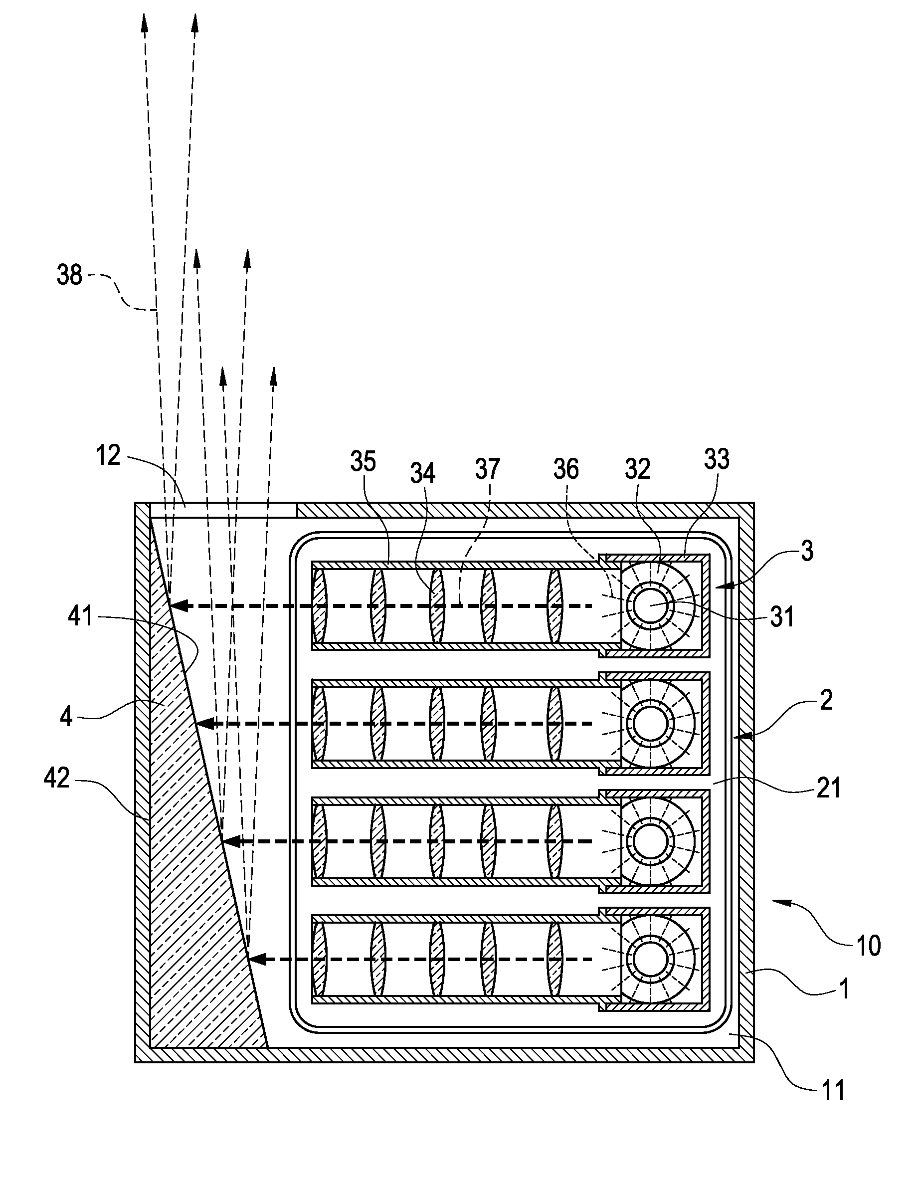
[0031]The technical characteristics, features and advantages of the present invention will become apparent in the following detailed description of the preferred embodiments with reference to the accompanying drawings. The drawings are provided for reference and illustration only, but not intended for limiting the present invention.

[0032]Referring to FIGS. 5 and 6 for a bottom view of a light source structure of the invention and a cross-sectional view of Section 6-6 as depicted in FIG. 5 respectively, a light source structure 10 of a backlight module comprises: a casing 1, a heat sink 2, a plurality of light source generators 3 and a first reflecting element 4. The foregoing assembly is a light source structure having a heat dissipating effect and capable of converting a spot light source into a linear light source, and the linear light source into a planar light source to be projected outside the casing 1.

[0033]The foregoing casing 1 has a containing space 11 for accommodating a p...


PUM


Abstract

A light source structure of a backlight module includes a casing, a heat sink, a plurality of light source generators, a first reflecting element and a second reflecting element. If a light emitting component of the light source generator is lit, a spot light source of the light emitting component is passed through an optical lens in a light pipe and converted into a linear light source to be projected onto an oblique surface of the first reflecting element. The oblique surface converts the linear light source into a planar light source to be projected from an opening of a casing to an oblique surface of the second reflecting element. The oblique surface of the second reflecting element guides the planar light source into the light guide plate, such that the light in the light guide plate is diffused uniformly to provide sufficient brightness to the light guide plate.

Description

BACKGROUND OF THE INVENTION[0001]1. Field of the Invention[0002]The present invention relates to a backlight module, and more particular to a backlight module that reflects a light source to a light guide plate by a multiple reflection.[0003]2. Description of Prior Art[0004]Since light crystal display (LCD) is not a self-emitting display device, an external light source is mandatory for achieving the display effect. Most liquid crystal displays adopt a backlight module to provide a uniform liquid crystal display panel and a high-brightness light source. The basic principle of the LCD adopts a spot light source or a linear light source, and effectively converts the spot or linear light source into a planar light source to provide a product emitting a planar light source with high brightness and uniform luminance.[0005]In general, a backlight module can be divided into two types: a front light type and a back light type, and the back light type can be classified and developed into the...

Claims


Application Information

Patent Timeline
IPC IPC(8): F21V7/04F21V29/00
CPCG02B6/0025G02B6/003G02B6/0031G02F2001/133628G02F1/133603G02F1/133615G02B6/0068G02F1/133628Y10S362/80Y10S385/901
Inventor WANG, PEI-CHOA
Owner PYROSWIFT HOLDING CO LIMITED
Why Eureka
Try Eureka