Battery pack

a battery pack and battery technology, applied in the direction of battery/fuel cell control arrangement, current conducting connection, cell components, etc., can solve the problems of not easy to cover the entire outer surface of a rectangular battery leaving only the electrode terminals exposed, and difficult to cover the external surface of a rectangular battery even more difficul

Inactive Publication Date: 2008-07-03
SANYO ELECTRIC CO LTD
View PDF3 Cites 132 Cited by
  • Summary
  • Abstract
  • Description
  • Claims
  • Application Information

AI Technical Summary

Benefits of technology

[0005]In prior art, separators are only sandwiched between surfaces of adjacent battery cells that would otherwise come in contact, and other regions of battery cell external cases are left exposed. Consequently, there is concern that adjacent battery cells could short circuit via their exposed regions. For a circular cylindrical battery, it is relatively easy to cover all but electrode terminal regions with material such as heat shrink tubing, but it is not easy to cover the entire outer surface of a rectangular battery leaving only the electrode terminals exposed. Further, since a safety valve, which releases gas if internal pressure rises abnormally, is provided on a rectangular battery, it is necessary to expose this type of safety valve as well as electrode terminals. This makes covering external surfaces of a rectangular battery even more difficult.

Problems solved by technology

Consequently, there is concern that adjacent battery cells could short circuit via their exposed regions.
For a circular cylindrical battery, it is relatively easy to cover all but electrode terminal regions with material such as heat shrink tubing, but it is not easy to cover the entire outer surface of a rectangular battery leaving only the electrode terminals exposed.
Further, since a safety valve, which releases gas if internal pressure rises abnormally, is provided on a rectangular battery, it is necessary to expose this type of safety valve as well as electrode terminals.
This makes covering external surfaces of a rectangular battery even more difficult.
Here there is concern, for example, that a tool dropped during assembly or unknowingly touched to an exposed terminal and metal surface of an external case could produce a short circuit or leakage current.
This type of sealing material can degrade over time or stress applied to the sealing material can result in an electrolyte leak.
In this case, there is concern that short circuit can occur via leaked electrolyte solution causing a conductive path between electrodes.

Method used


Image

  • Battery pack
  • Battery pack
  • Battery pack

Examples


first form of embodiment

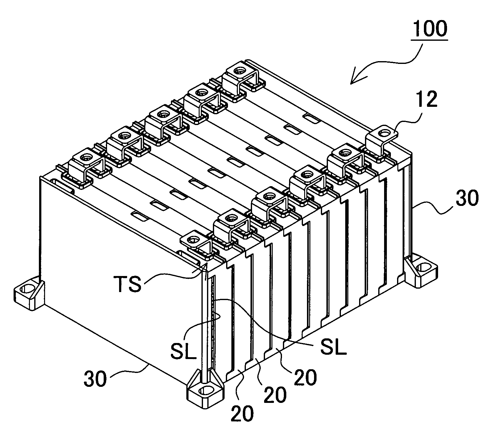
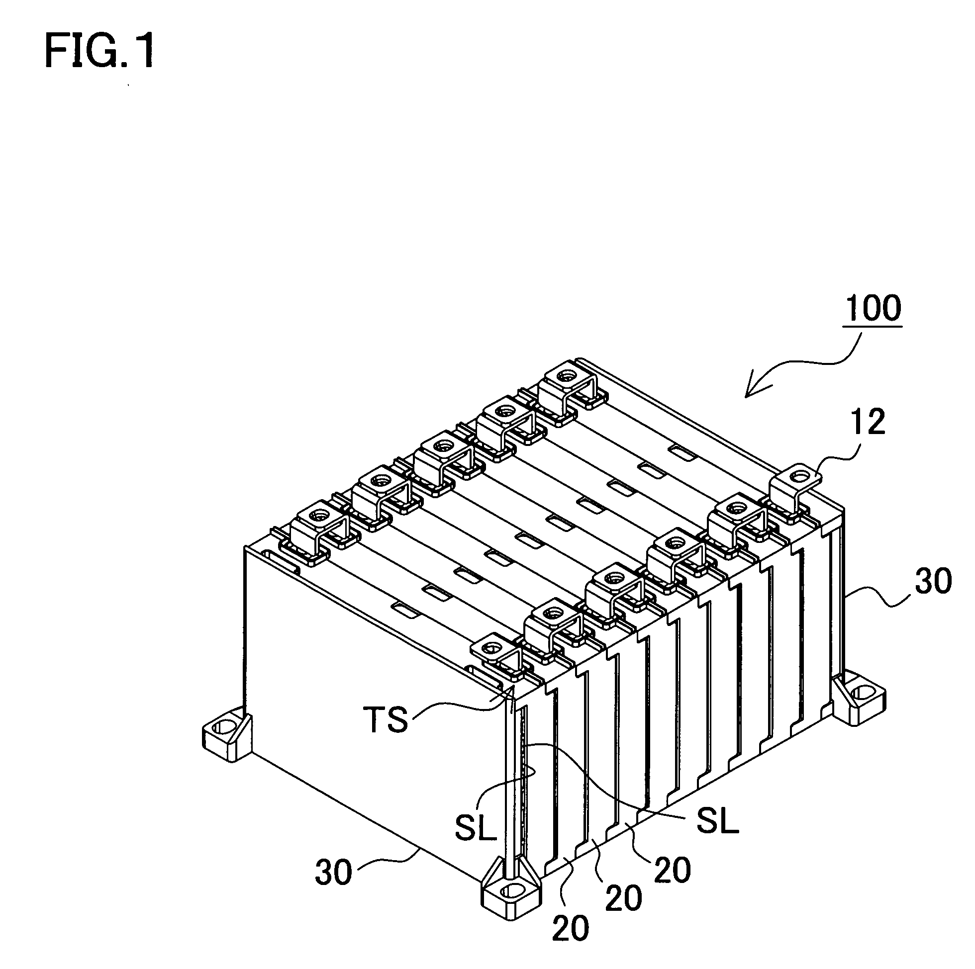
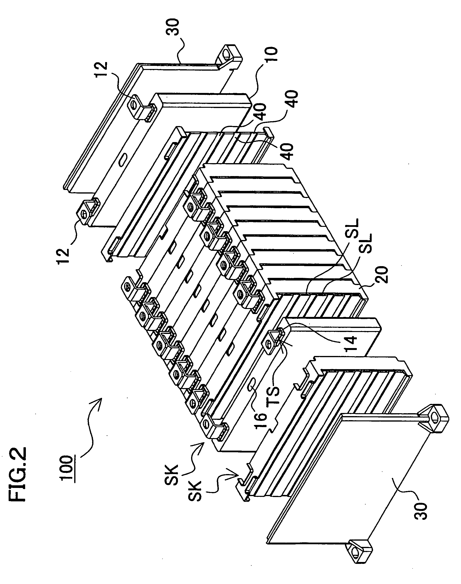
[0047]FIG. 1 shows an oblique view of the exterior of a battery pack 100 for the first form of embodiment of the present invention, FIG. 2 shows an exploded oblique view of that battery pack 100, FIG. 3 shows a side view of that battery pack 100, FIG. 4 shows oblique views of a separator 20, and FIG. 5 shows three other views of a separator 20. In FIG. 4, (a) shows an oblique view from the backside of the bottom surface plate, and (b) shows an oblique view from the front side, that is the open region side of the bottom surface plate of the separator. In FIG. 5, (a) shows a plan view, (b) shows a front view, and (c) shows a side view of the separator. The battery pack100 shown in these figures is configured by stacking side-by-side a plurality of battery cells 10 and separators 20 in an alternating fashion and covering right and left end planes with end plates 30. Specifically, box shaped separators 20 are fit together to form holding spaces SK between separators 20 that house rectan...

second form of embodiment

[0057]A configuration to discharge electrolyte from reservoir regions can also be provided. FIG. 7 shows an enlarged oblique view of terminal feed-through opening TS regions of a battery pack 200 for the second form of embodiment. In FIG. 8, (a) shows a plan view of the separator 20B, (b) shows a front view of the separator 20B, and (c) shows a side view of the separator 20B for the second form of embodiment. One section of the terminal sidewalls 27 shown in these figures can be opened and drain sidewalls 28 can be established that extend to a side surface of the separator 20B. The drain sidewalls 28 form a discharge path for the electrolyte. With this arrangement, drain sidewalls 28 can guide electrolyte collected in a reservoir region TR to a side surface of the separator 20B for safe discharge. This can safely discharge electrolyte while avoiding short circuit due to the spread of the electrolyte.

(Stepped Region Depressions 40)

[0058]A separator 20 has stepped region depressions 4...

third form of embodiment

[0061]The interconnecting structure is not limited to fitting interlocking projections and grooves together as described above, and various schemes to suitably link separators can be adopted. As an example of another interconnecting structure, interlocking projections alternately protruding from the rim of the open region of a separator and corresponding interlocking grooves also alternately established can form an interlocking finger structure. A battery pack 300 for the third form of embodiment is an example of this type of interconnecting structure and is shown in FIGS. 9-13. In these figures, FIG. 9 shows an oblique view of the battery pack 300, FIG. 10 shows an exploded oblique view, FIG. 11 shows a side view, FIG. 12 shows and oblique view of a separator 20C, and FIG. 13 shows three views of a separator 20C. The battery pack 300 shown in these figures is configured in the same fashion as the first form of embodiment with a plurality of battery cells 10 and separators 20C alter...


PUM

PropertyMeasurementUnit
electricalaaaaaaaaaa
thermal insulting propertiesaaaaaaaaaa
sizesaaaaaaaaaa

Abstract

In a battery pack having a plurality of battery cells 10 connected in series and / or parallel, the battery pack is provided with a plurality of battery cells 10 each encased in a rectangular external case, and a plurality of separators 20 with electrical and heat insulating properties covering the outside of each battery cell external case excluding electrode terminals 12. Each separator 20 is disposed to intervene between adjacent battery cells 10 putting the external cases of those battery cells 10 in contact with both sides of the separator 20. With the external case of each battery cell 10 covered by separators 20 while exposing electrode terminals 12, those electrode terminals 12 are connected together. As a result, excluding required regions, battery cells 10 can be enclosed and unintended events such as short circuits can be effectively prevented.

Description

BACKGROUND OF THE INVENTION[0001]1. Field of the Invention[0002]This invention relates to a battery pack having a plurality of rectangular batteries connected in series and / or parallel, and in particular to a battery pack used in a battery driven vehicle such as a hybrid electric vehicle (HEV) or a pure electric vehicle (PEV).[0003]2. Description of the Related Art[0004]Higher output in a limited space is sought for a battery pack or battery array used as a power source in an electric vehicle or hybrid car. Consequently, rectangular batteries have been used, which have energy density superior to that of circular cylindrical batteries. However, in this type of battery pack with a plurality of rectangular batteries connected in series and / or parallel adjacent rectangular battery cells are in close disposition. Therefore, the ability to efficiently radiate heat is imperative. In particular, lithium ion batteries can for some reason experience thermal runaway, and separators are used to...

Claims


Application Information

Patent Timeline
Patent Type & Authority Applications(United States)
IPC IPC(8): H01M2/10H01M50/103H01M50/209H01M50/291H01M50/293H01M50/55H01M50/553
CPCB60L3/0046Y02T10/7061B60L11/1864B60L11/1874B60L11/1879H01M2/0237H01M2/0242H01M2/0245H01M2/1005H01M2/1061H01M2/1077H01M2/1083H01M2/20H01M2/30Y02T10/7005B60L11/1855B60L58/19B60L58/21B60L58/26B60L50/64Y02T10/70Y02E60/10H01M50/258H01M50/209H01M50/293H01M50/103H01M50/291H01M50/55H01M50/553
Inventor OKADA, WATARUYANO, JUNYA
Owner SANYO ELECTRIC CO LTD
Why Eureka
Try Eureka