Method to measure tool wear from process model parameters

a process model and parameter technology, applied in the field of tool wear measurement, can solve the problems of inability to determine when the tool wear is excessive, no well established guidelines, and the dual (sharp vs. dull tool) spindle power recording process is too cumbersome, so as to facilitate the access of spindle power and facilitate the measurement of tool wear

Inactive Publication Date: 2008-07-03
UNIVERSITY OF NEW HAMPSHIRE
View PDF8 Cites 30 Cited by
  • Summary
  • Abstract
  • Description
  • Claims
  • Application Information

AI Technical Summary

Benefits of technology

[0010]The instant invention is a system and method for monitoring tool wear in CNC machining operations by monitoring spindle power and extracting instantaneous cutting geometry. The method is based on a physics-based two parameter process model and measuring at least two different cutting conditions. The process model parameters are measured with easily accessible spindle power. In contrast to spindle power alone which is influenced

Problems solved by technology

It has been recognized that there are a number of deficiencies in the current industrial practice of monitoring tool wear via spindle power.
In addition, the selection of a suitable offset for the spindle power alarm is problematic.
There are no well established guidelines to determine when the tool wear is excessive.
But often several different tools are used to complete the machining of a particular part making the dual (sharp vs. dull tool) s

Method used


Image

  • Method to measure tool wear from process model parameters
  • Method to measure tool wear from process model parameters
  • Method to measure tool wear from process model parameters

Examples


Embodiment Construction

[0030]The present invention uses process model parameters in place of spindle power to monitor the state of tool wear. The use of process model parameters removes the dependence of the wear criterion on part geometry and also provides a useful mechanism to distinguish between different tool wear mechanisms. Slowly varying tool wear mechanisms, such as flank wear, can be monitored in a progressive fashion with one class of process model parameters while another class of process model parameters can provide a precursor alert when more precipitous wear mechanisms (e.g. notch or crate wear) dominate.

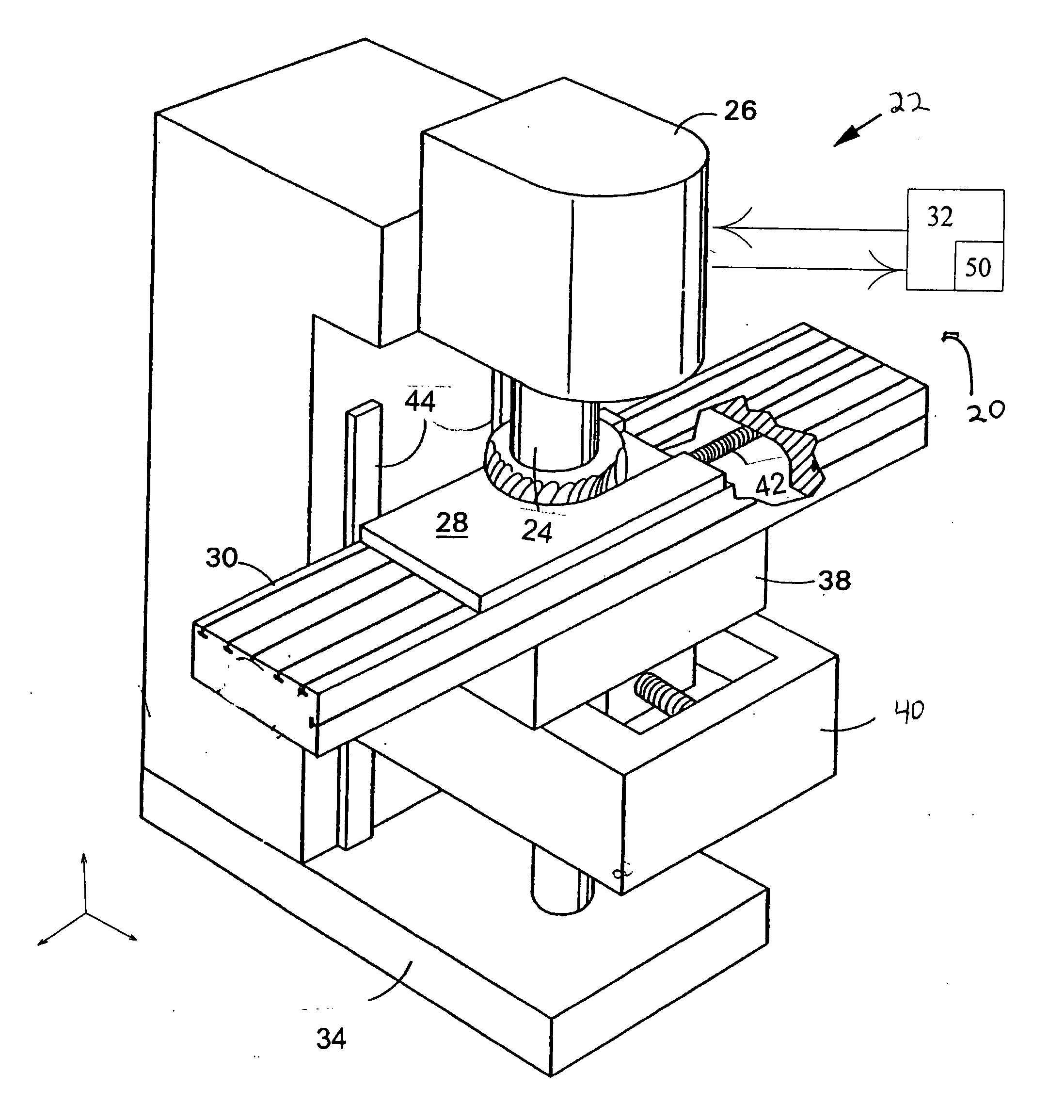
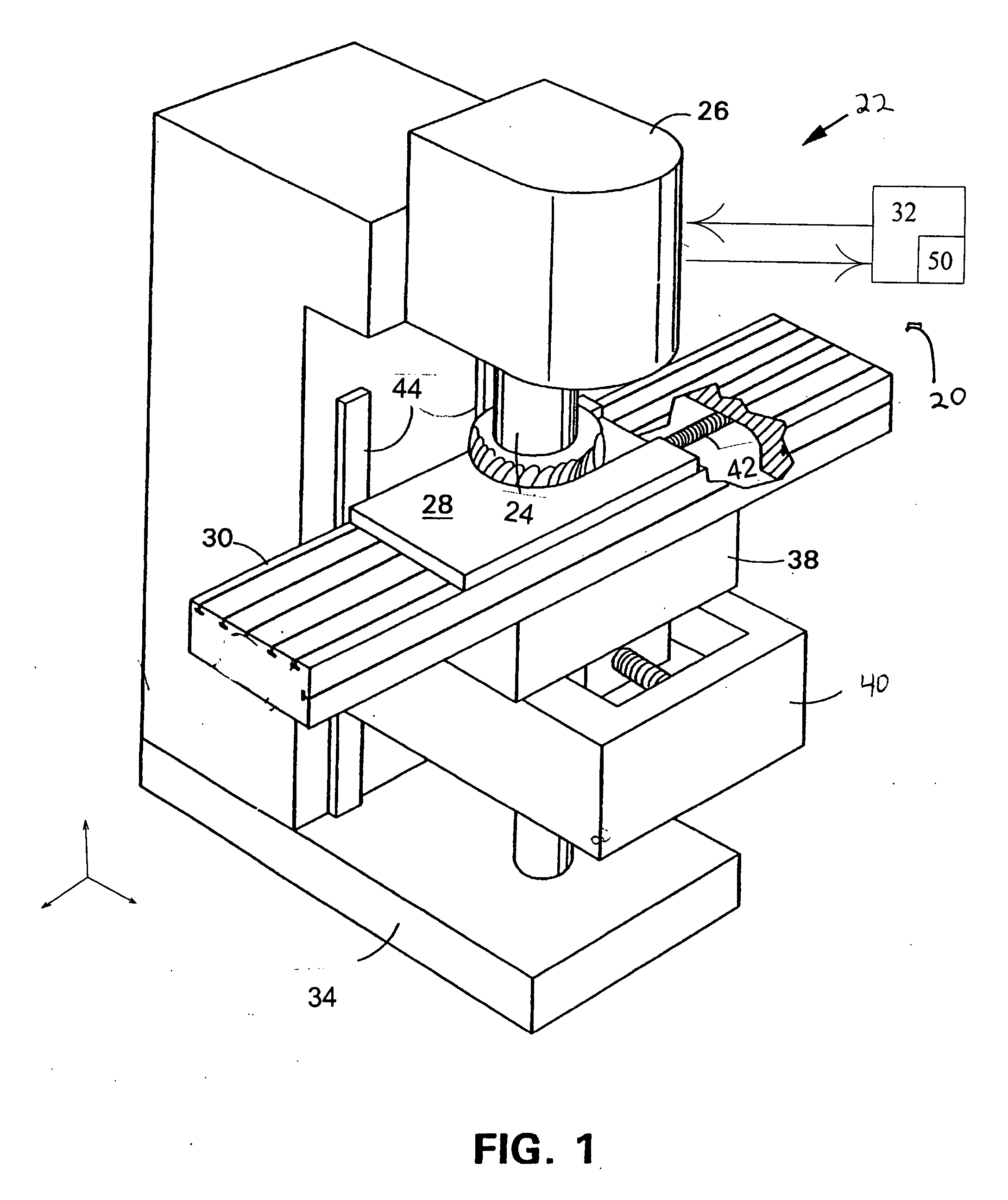
[0031]Referring to FIG. 1, a perspective view of a tool wear system 20 with a typical three axis milling (metal removal) machine 22 is shown. The tool wear system 20 has a machine tool such as the milling machine 22 with a tool 24. The tool 24 is held by a machine head 26 of the milling machine 22. The tool 24 operates on a work piece 28. The work piece 28 is held by clamps or other methods ...


PUM


Abstract

A system and method for monitoring tool wear in CNC machining operations by monitoring spindle power and extracting instantaneous cutting geometry. The method is based on a physics-based two parameter process model and measuring at two different cutting conditions. The process model parameters are measured with easily accessible spindle power. In contrast to spindle power alone which is influenced by many factors, most especially by variable cutting conditions and by the tool condition, the process model parameters are independent of the geometrically variable cutting conditions and provide a simple and direct measure of tool wear. The two process model parameters change differently depending on the mechanism of the tool wear, specifically flank wear versus cutting edge degradation. This provides a diagnostic for tool wear.

Description

CROSS REFERENCE TO RELATED APPLICATIONS[0001]The present application claims the benefit of Provisional Patent Application Ser. No. 60 / 872,151 filed Dec. 1, 2006, which is incorporated herein by reference.GOVERNMENT LICENSE RIGHTS[0002]The U.S. Government has a paid-up license in this invention and the right in limited circumstances to require the patent owner to license others on reasonable terms as provided for by the terms of contract number, DMII-0322869 awarded by the National Science Foundation.TECHNICAL FIELD[0003]The present invention relates to a mechanism to measure tool wear on a machine tool such as on a computer numerical control (“CNC”) metal removal machine.BACKGROUND OF THE INVENTION[0004]There are a variety of tool wear mechanisms. These are commonly described as flank wear (a gradual loss of the rubbing face of the tool), notch wear (relatively sharp indentations in the cutting edge), crater wear (pits or holes forming on the cutting face of the tool), cracking, chi...

Claims


Application Information

Patent Timeline
IPC IPC(8): G06F17/00
CPCG05B19/4065G05B2219/50321G05B2219/50319G05B2219/37258
Inventor JERARD, ROBERT B.ESTERLING, DONALDFUSSELL, BARRY K.XU, MINSCHUYLER, CHAD
Owner UNIVERSITY OF NEW HAMPSHIRE
Why Eureka
Try Eureka