
Leak detector for a pressurized cylinder

a technology of leak detector and pressurized cylinder, which is applied in the measurement of fluid loss/gain rate, fluid tightness measurement, instruments, etc., can solve the problems of shock absorber or landing gear of an airplane, and affecting the safety of passengers

Inactive Publication Date: 2008-07-10
KULITE SEMICON PRODS
View PDF3 Cites 29 Cited by
  • Summary
  • Abstract
  • Description
  • Claims
  • Application Information

AI Technical Summary

Problems solved by technology

In regard to the above, a much more complicated situation occurs when the volume (V) of the container changes over time.
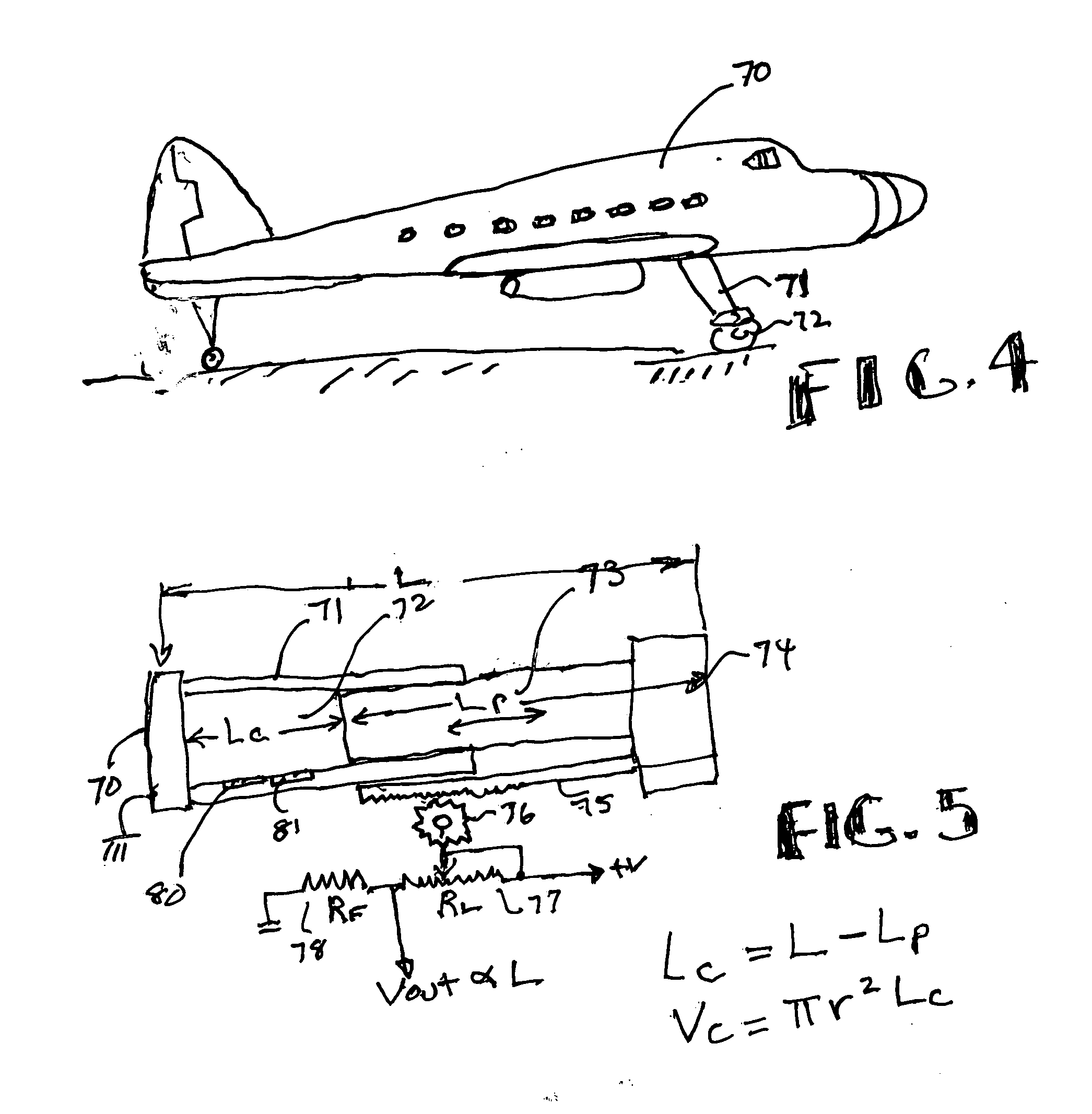
One specific application which can create major problems is the detection of leaks in a shock absorber, such as those used in aircraft or in automobiles.
While a leak in an automobile shock absorber is typically not a life threatening event, a leak in a shock absorber or a landing gear of an airplane can be catastrophic and should be quickly identified.

Method used


Image

  • Leak detector for a pressurized cylinder
  • Leak detector for a pressurized cylinder
  • Leak detector for a pressurized cylinder

Examples


Embodiment Construction

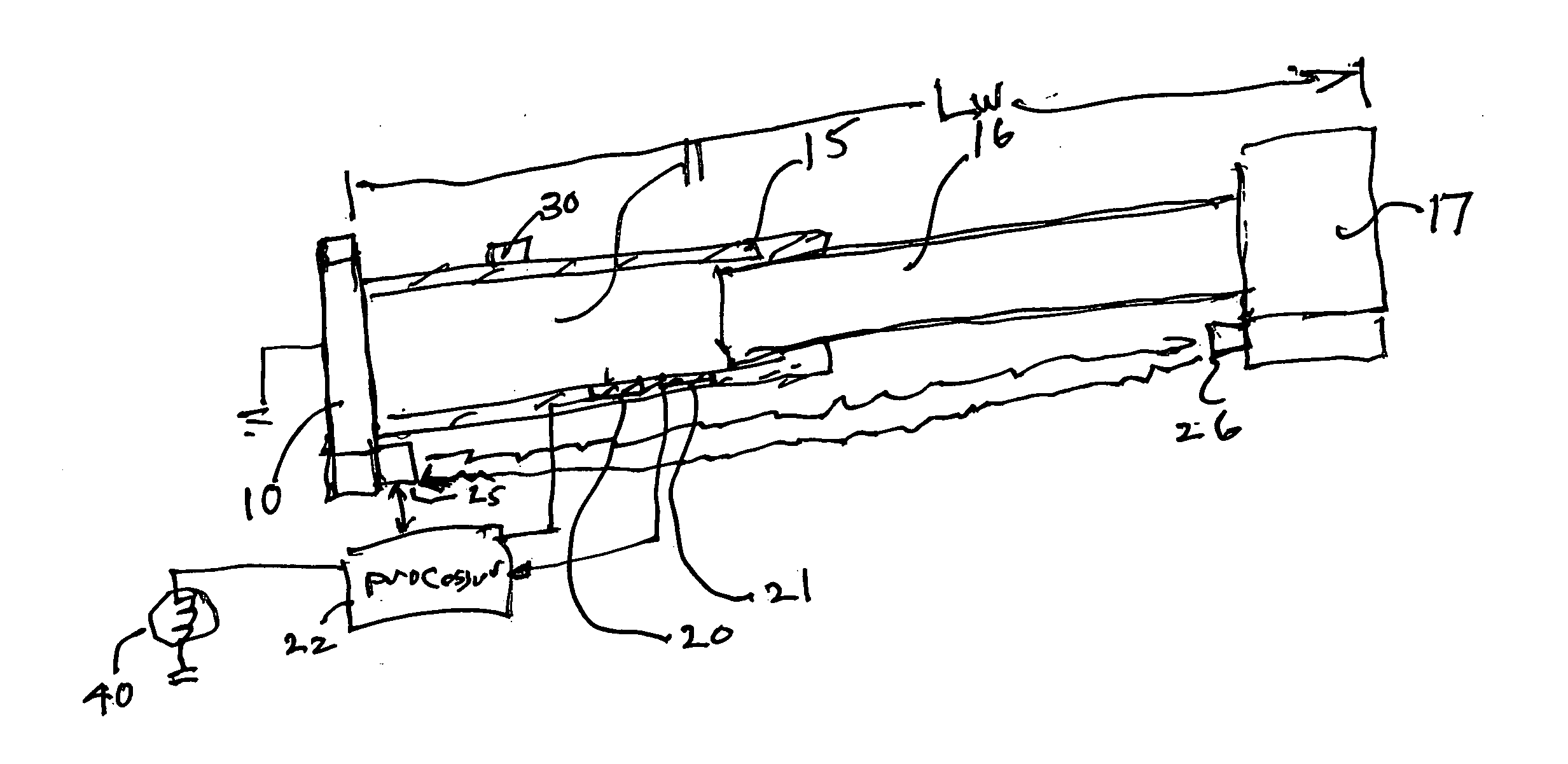
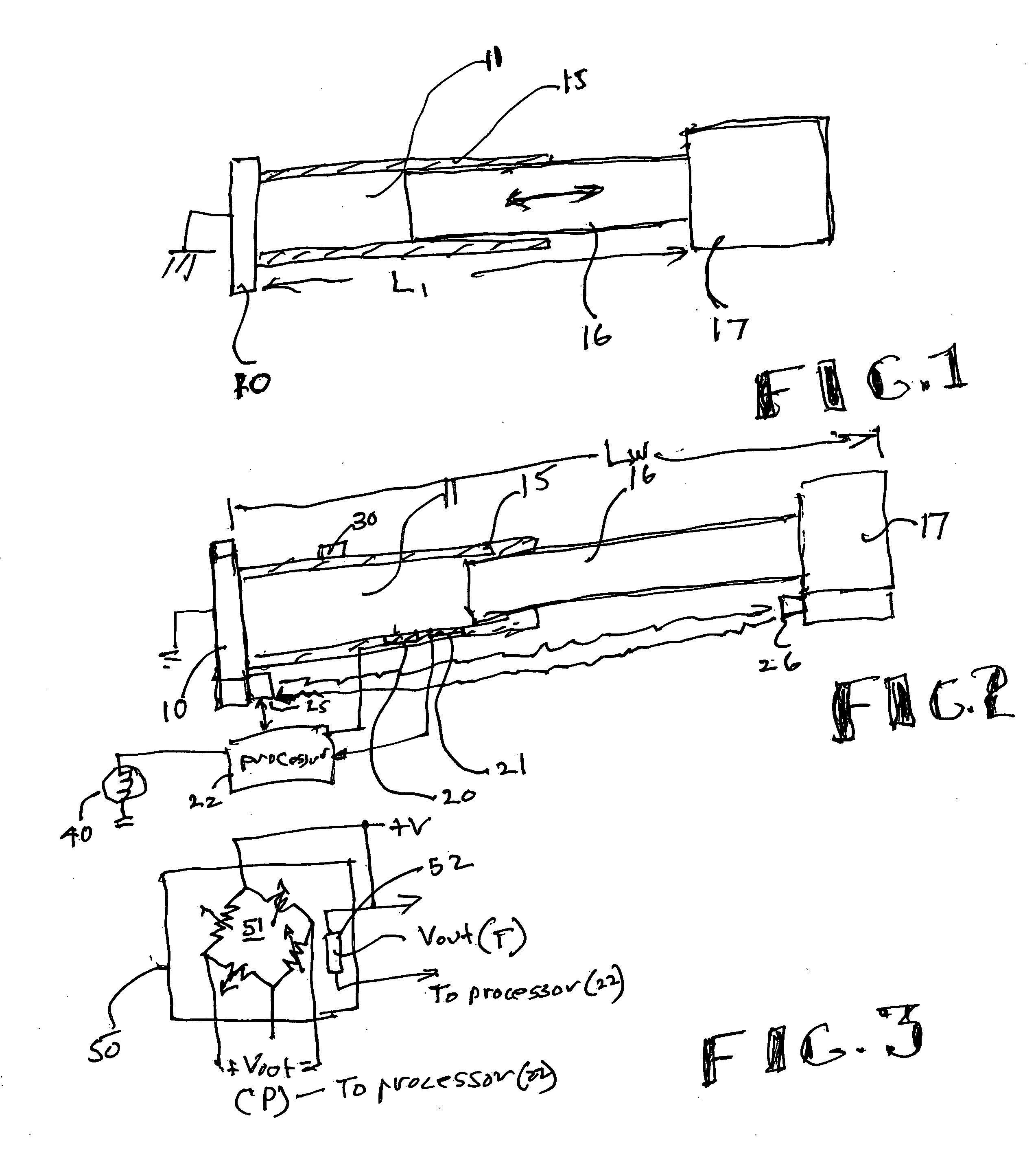
[0020]Referring to FIG. 1, there is shown a pressurized cylinder such as those employed in an aircraft shock absorber or an aircraft landing gear in which the displacement or length changes during normal operation. As seen in FIG. 1 there is fixed end or base 10 which basically is associated with a cylindrical member 15. Positioned within the cylindrical member 15, is a piston 16 which moves slidably in the direction of the arrows depicted. The piston 16 is associated with a mass 17 which may be a damped mass and may be coupled to the wheel or tire of an aircraft or an automobile when employed as a shock absorber. There is a gas or fluid 11a located in the cavity 11 formed between the piston face and cylinder wall. The gas in the cavity compresses or expands depending on the position of the piston in the cylinder 15. If the mechanism shown in FIG. 1 is employed as a landing gear or a shock absorber for an aircraft, when the aircraft is on the ground a great weight is applied to the ...


PUM


Abstract

A leak detector apparatus for a pressurized cylinder having a cylinder of a radius (r) with a slidable piston in the cylinder with a gas filled chamber positioned between a cylinder end and the piston face. The length (L) of the chamber is calculated according to load changes on the piston where the volume (Vc) of the chamber changes. The pressure and temperature of the chamber are measured as well as the length. These values are inputted to a processor to solve the ideal gas law equation PV=nRT where a change in n for a change in length indicates a leak.

Description

FIELD OF THE INVENTION[0001]This invention relates to the detection of fluid leaks in a container and more particularly to detection of a fluid leak in a pressurized cylinder.BACKGROUND OF THE INVENTION[0002]Measuring the leak rate of a fluid in a sealed container is a very important procedure in many different applications. One can measure the leak rate in a pressurized gas bottle to determine whether or not the bottle exhibits a leak after a pressurized gas is placed in the bottle. As one can ascertain, for a fixed volume container one can measure the leak rate by measuring the pressure and temperature inside the container. By using the ideal gas law, which is PV=nRT (or for higher pressure the Van der Waals equation), it is easy to see that taking the ratio of pressure to temperature P / T gives a measure of the molar density (n / V) which only changes with a leak in the system. This is a well known principle and the assignee herein, namely Kulite Semiconductor Products, Inc. has a n...

Claims


Application Information

Patent Timeline
Patent Type & Authority Applications(United States)
IPC IPC(8): G01M3/26G01M3/34
CPCG01M3/3236B64C25/60
Inventor KURTZ, ANTHONY D.DEWEERT, JOSEPH VANMARTIN, RICHARD J.
Owner KULITE SEMICON PRODS
Learn More