Boundary-Layer-Ingesting Inlet Flow Control System

a flow control system and boundary layer technology, applied in the direction of machines/engines, air-flow influencers, instruments, etc., can solve the problems of increasing the technical risk of configuration, difficult inlet design, and complex performance assessment of such a highly integrated propulsion system, so as to reduce aerodynamic interface distortion and minimize the negative impact of active flow control

Inactive Publication Date: 2008-07-10
NASA
View PDF20 Cites 26 Cited by
  • Summary
  • Abstract
  • Description
  • Claims
  • Application Information

AI Technical Summary

Benefits of technology

[0009]In view of the deficiencies described above, it is an object of the present invention to provide a BLI inlet flow control system for reducing aerodynamic interface distortion across the range of inlet flow conditions while minimizing the negative impacts of active flow control.
[0012]The reason for combining these two types of flow control devices was to balance the strength and weaknesses of each device. The active flow control jets require a significant amount of mass flow rate to effectively reduce the inlet distortion, but do not depend on the velocity of the onset flow to create a flow deflection force and can vary their strength by increasing or decreasing the mass flow rate of the jet. The vortex generating vanes do not require any external supply of mass flow rate to effectively reduce the inlet distortion, but do depend on the onset flow velocity to create a flow deflection force. Together, the vortex generating vanes can reduce most of the inlet distortion and the active flow control jets can be utilized at significantly reduced control jet mass flow rates. The hybrid jet / VG flow control system can operate effectively over a larger operation range by varying the amount of jet mass flow to keep the distortion in acceptable range.

Problems solved by technology

These impacts include aircraft noise and emissions pollution around airports and emissions at altitude.
However, the incorporation of the inlets on the surface of the vehicle increases the technical risk of the configuration.
Since the boundary layer on the BWB is expected to be on the order of about 30% of the inlet height, this presents a challenging task for inlet design.
In addition, the performance assessment of such a highly-integrated propulsion system is a complex undertaking, requiring the simultaneous examination of many influential factors in order to determine whether BLI provides a benefit from a system standpoint.
However, in order for the engine to operate in the BLI environment, a minimum distortion level must be achieved even at the cost of reduced efficiency.
The effect of BLI on engine performance is known to be detrimental because BLI increases the distortion and reduces the pressure recovery at the engine fan-face.
A drawback of vortex generating vanes or other forms of passive flow control devices is that they are generally optimized around a small envelope and thus become less effective when the inlet conditions are outside of that envelope.
Other drawbacks for passive flow control include increased losses of the inlet flow since passive devices extract energy from the flow for control.
Known drawbacks of active flow control include the losses to engine efficiency due to the amount of inlet mass flow required to drive the flow control and the added complexity of plumbing and operating the active flow control.

Method used


Image

  • Boundary-Layer-Ingesting Inlet Flow Control System
  • Boundary-Layer-Ingesting Inlet Flow Control System
  • Boundary-Layer-Ingesting Inlet Flow Control System

Examples


Embodiment Construction

[0019]While this invention is susceptible of embodiments in many different forms, there are shown in the drawings and will herein be described in detail, preferred embodiments of the invention with the understanding that the present disclosure is to be considered as an exemplification of the principles of the invention and is not intended to limit the broad aspect of the invention to the embodiments illustrated.

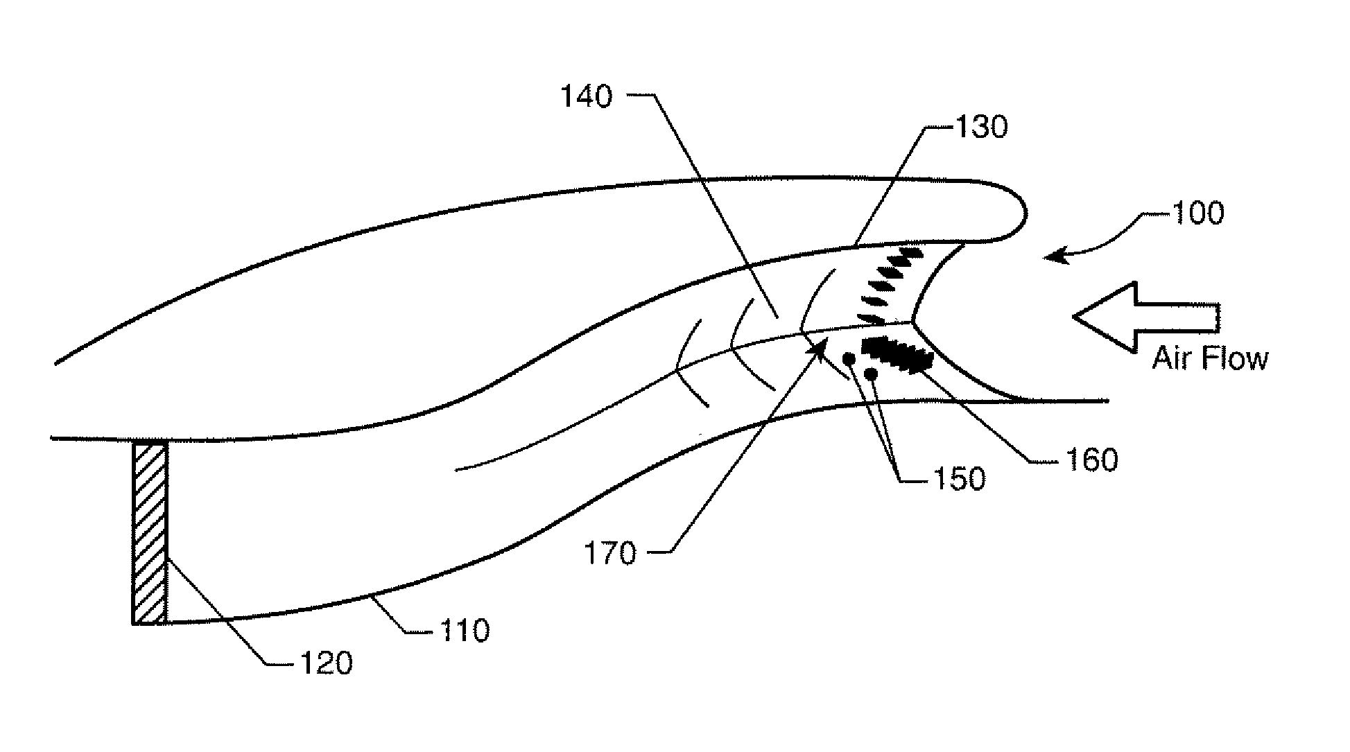
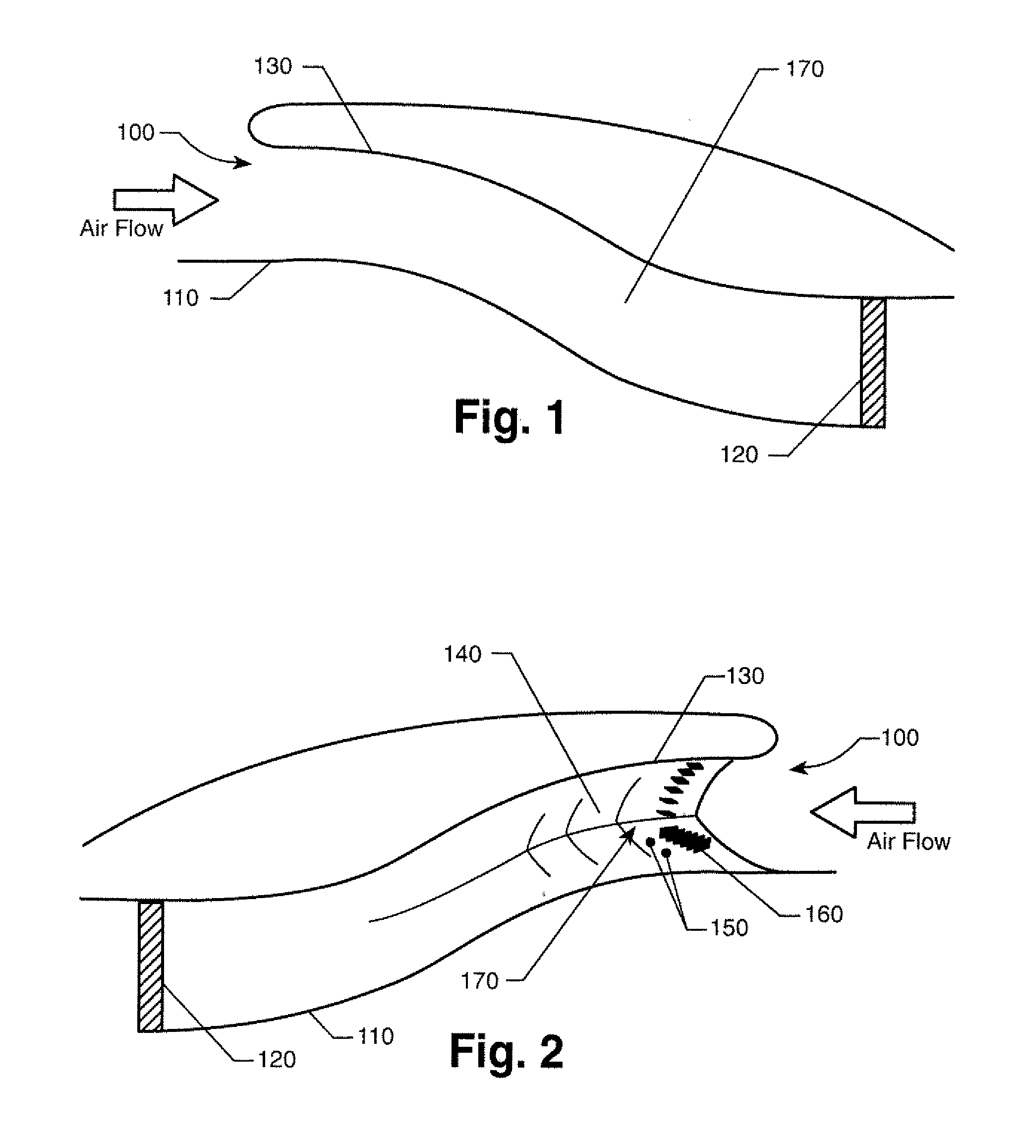
[0020]FIG. 1 shows a side view cross section of a boundary-layer-ingesting inlet as used in the present invention. As shown, the BLI inlet 100 is described as generally having a serpentine or “S” shape which leads to the aircraft engine. The front face of the engine can be referred to as the aerodynamic interface plane (AIP) 120.

[0021]Distortion across the AIP, both radially and circumferentially, can greatly affect engine performance. Preferably, circumferential distortion, measured and described using the average SAE circumferential distortion descriptor, DPCPavg has a valu...


PUM


Abstract

A system for reducing distortion at the aerodynamic interface plane of a boundary-layer-ingesting inlet using a combination of active and passive flow control devices is disclosed. Active flow control jets and vortex generating vanes are used in combination to reduce distortion across a range of inlet operating conditions. Together, the vortex generating vanes can reduce most of the inlet distortion and the active flow control jets can be used at a significantly reduced control jet mass flow rate to make sure the inlet distortion stays low as the inlet mass flow rate varies. Overall inlet distortion, measured and described as average SAE circumferential distortion descriptor, was maintained at a value of 0.02 or less. Advantageous arrangements and orientations of the active flow control jets and the vortex generating vanes were developed using computational fluid dynamics simulations and wind tunnel experimentations.

Description

ORIGIN OF THE INVENTION[0001]The invention described herein was made by employees of the United States Government and may be manufactured and used by or for the Government for Government purposes without payment of any royalties thereon or therefore. This application claims the benefit of U.S. Provisional Patent Application No. 60 / 883,396, filed Jan. 4, 2007, which is hereby incorporated by reference in its entirety.BACKGROUND OF THE INVENTION[0002]The present invention relates to boundary-layer-ingesting inlets for aircraft engines and more specifically a system for reducing distortion at the aerodynamic interface plane using a combination of active and passive flow control devices.[0003]The effect of aviation on the environment and in particular global warming has recently become a focus of study. This study considers the three primary impacts that civil aviation has on the environment. These impacts include aircraft noise and emissions pollution around airports and emissions at a...

Claims


Application Information

Patent Timeline
Patent Type & Authority Applications(United States)
IPC IPC(8): B64D33/02G06G7/57F15D1/00
CPCB64D33/02B64D2033/0226B64D2033/0273B64C2230/18F15D1/001F15D1/12Y02T50/166F15D1/0005Y02T50/10Y10T137/0391Y10T137/0536Y10T137/0645
Inventor OWENS, LEWIS R.ALLAN, BRIAN G.
Owner NASA
Why Eureka
Try Eureka