Multi-channel spectrum analyzer

a spectrum analyzer and multi-channel technology, applied in the field of spectrum analyzers, can solve the problems of complex construction, inability to complete spatial linearization of spectrum, and inability to address the situation of different wavelengths

Active Publication Date: 2008-01-01
P&P OPTICA INC
View PDF62 Cites 20 Cited by
  • Summary
  • Abstract
  • Description
  • Claims
  • Application Information

AI Technical Summary

Benefits of technology

[0023]In one broad aspect, the present invention is directed to the configuration of a spectrometer, which minimizes the negative impact of the grating position on performance of the spectrometer through the selection of an optimal configuration of the grating position in a spectrum disperser, and produces constant size images of slit for all wavelengths of spectral bands up to one octave wide in any part of an about 400 nm to about 2500 nm spectral range.
[0033]In another broad aspect, the present invention is directed to the production of the multi-channel or line imaging spectrometer containing a smaller number of easier to produce optical lenses that can be made of a small number of optical materials.
[0034]The main advantages of a spectrometer designed in accordance with an embodiment of the present invention may become particularly apparent in applications for the simultaneous analysis of spectra from different targets or different points of the same target, especially if the target (e.g. humans) demonstrates spatial instabilities. A proper design of radiation collecting optics becomes crucial in these kinds of applications if optimal extraction of required information is to be attained. Therefore, in yet another broad aspect, the present invention is directed to a radiation collecting system for a multi-channel spectrum analyzer designed in accordance with an embodiment of the present invention, allowing for optimal use of the analyzer.
[0037]The focusing objective in this embodiment is designed to produce a high resolution, flat, undistorted spectral image of the slit, with constant, wavelength independent magnification for a spectral band about one octave wide placed anywhere between about 400 nm and about 2500 nm of spectral range. In this embodiment, this is achieved with an objective, consisting of three lenses: a relatively thin positive front lens; a very thick, rod-like, negative meniscus made of material with a higher refractive index than the front lens; and a relatively thin, positive back lens made of the same material as the front lens. Both the refractive properties of the glasses and the axial thickness of the lenses were selected to produce a focusing objective which simultaneously secures a substantially constant sized focal spot for all wavelengths across the selected working spectral band, and a wavelength independent, constant size slit image projected on a flat surface of a photodetector array, essentially perpendicular to the fan axis of the diffracted radiation. Remnant positional chromaticity of the wide diffracted beams is corrected by the appropriate selection of suitable glasses which forces it to vary linearly with the position on the array; the impact of this chromaticity is eliminated by introducing a small tilt to essentially perpendicular to the axis photodetector array and a corresponding longitudinal and lateral shift of the array, different for different spectral working bands. This degree of freedom allows for the application of the designed objective in any part of the about 400 nm to about 2500 nm spectral range under the condition that the used spectral band is not substantially wider than one octave.
[0038]The present inventors realized that the linear dependence of the positional chromaticity on the surface of the detector array does not ensure linearity of spectral dispersion; therefore, if there exist three spectral components, with wavelength of the second midway between the wavelengths of the first and third components, the focal spot of the second spectral component is not necessarily placed at the midway between the remaining two. It was realized that linear wavelength calibration may not be sufficient for some applications, and a more complex, higher order calibration based on several wavelengths may need to be applied in such cases. This may be unavoidable if the same, relatively simple focusing objective (possibly with antireflection coatings optimized for a working spectral band) in different regions of a wide spectral range is to be used; however, such an objective improves performance and significantly simplifies production process, thereby contributing to the reduction of spectrometer production costs.
[0040]In variant embodiments of the invention objectives can be used in conjunction with reflective gratings, when the dispersion of the grating, selected working spectral range and configuration of the spectrometer eliminate the problem of the physical interference of the collimating and focusing optics.

Problems solved by technology

It is generally understood that complete spatial linearization of the spectrum is impossible and high resolution spectrometers have to be individually wavelength calibrated.
There are also known optical systems (as, for example, microscopic objectives), which correct optical aberrations introduced by plane parallel glass plate (cover glass) for all wavelengths traversing the cover glass along the same path; however, none of these address the situation where different wavelengths take different paths.
Since such objectives simultaneously satisfy conditions for achromats, aplanats and anastigmats, they have quite complex construction, and usually at a minimum contain five lenses made of more than two optical glasses.
Because of the large number of elements with large curvature (short radii of curvature), such objectives can cause significant loss of radiation and produce significant background of the scattered radiation.
Since they also do not take into consideration the fact that in spectrometers, the beams of different wavelengths travel different optical paths, such objectives do not utilize all design potential for such applications.

Method used


Image

  • Multi-channel spectrum analyzer
  • Multi-channel spectrum analyzer
  • Multi-channel spectrum analyzer

Examples


Embodiment Construction

[0048]The terms “spectrum analyzer” and “spectrometer” are used interchangeably in the description and in the claims.

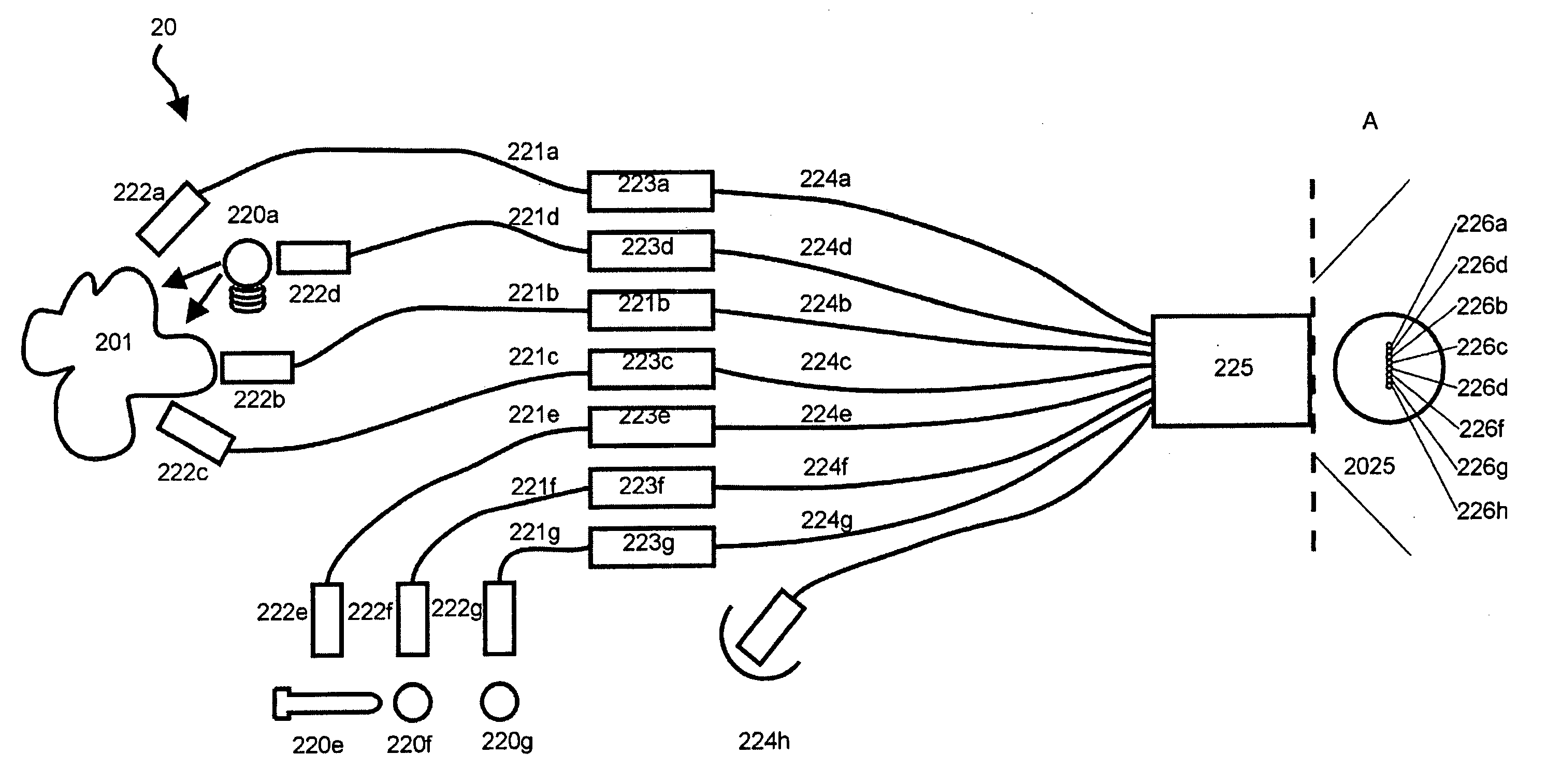
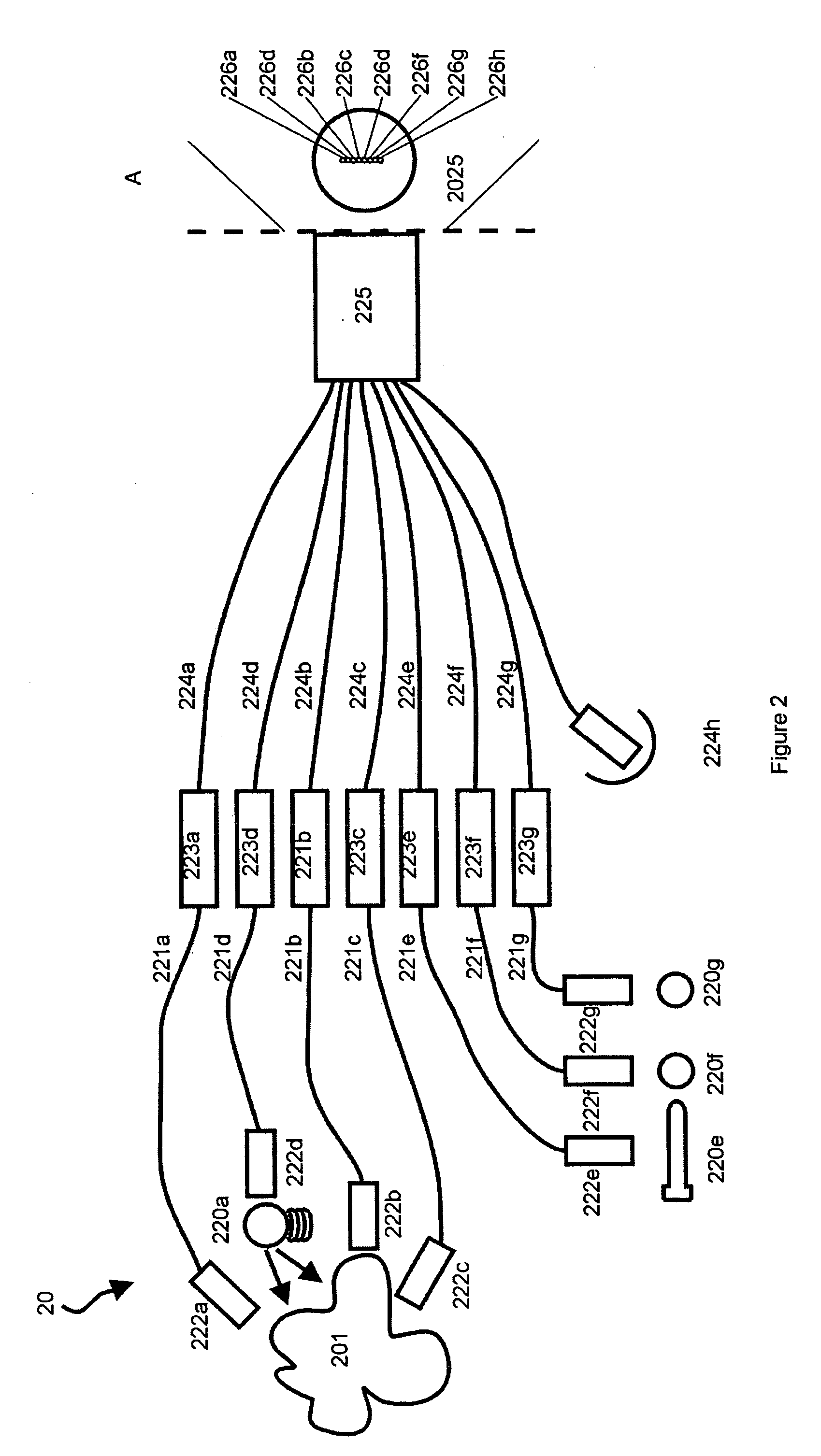
[0049]In one aspect, the present invention provides a high performance, multi-channel (also referred to herein as a line imaging spectrum analyzer) for simultaneous registration of spectra of radiation delivered to any point arranged along a piece of straight line, referred to herein as a slit-like entry port (or slit) of the spectrum disperser. It is well known that the majority of existing spectrophotometers with gratings or prisms are not built to resolve spectral differences of radiation delivered to different points of the slit, and that they generally provide information only about spectral properties of the total radiation delivered. Such instruments are easier to build and are satisfactory for many applications. There exist applications, however, when comparison of spectral composition of radiation produced at different points of the direct or indirect source ...


PUM


Abstract

A spectrum analyzer for the simultaneous analysis of electromagnetic radiation delivered to it from either multiple sources or from a linear segment along a source surface, and arranged as either continuous or discrete set of points along a short piece of a straight line referred to herein as a slit. In one embodiment of the invention, the optical design of the dispersing part of the analyzer provides essentially stigmatic spots for any spectral band up to one octave wide in the spectral range of about 400 nm to about 2500 nm.

Description

FIELD OF THE INVENTION[0001]The present invention relates generally to spectrum analyzers and more specifically to devices adapted to analyze the spectral composition of electromagnetic radiation in near ultraviolet, visible and near infrared spectral bands of electromagnetic radiation, delivered to an entry port of the device in a form of a narrow slit, simultaneously for each point of the slit.BACKGROUND OF THE INVENTION[0002]In many fields, biology and medicine in particular, there is a rapidly increasing need for a simultaneous spectral analysis of electromagnetic radiation produced by individual points of a radiation source, radiation produced by different sources or produced by one or more sources and affected by different points of an extended object, such as different locations or parts of a human body, for example. The need becomes especially critical in optical spectral tomography of continuously varying or changing systems such as a living human body. To address these pro...

Claims


Application Information

Patent Timeline
Patent Type & Authority Patents(United States)
IPC IPC(8): G01J3/28G01J3/02G01J3/18
CPCG01J3/02G01J3/18G01J3/2803G01J3/0208G01J3/0294
Inventor KRYSZCZYNSKI, TADEUSZPAWLUCZYK, OLGAPAWLUCZYK, RAFAL
Owner P&P OPTICA INC
Why Eureka
Try Eureka