Position Detection System

a detection system and position technology, applied in the field of system for detecting the position of objects, can solve the problems of inability to specify the combination of xb> and xb>, and the difficulty of setting

Active Publication Date: 2008-07-10
KONAMI DIGITAL ENTERTAINMENT CO LTD
View PDF5 Cites 53 Cited by
  • Summary
  • Abstract
  • Description
  • Claims
  • Application Information

AI Technical Summary

Benefits of technology

[0033]For example, it becomes possible to specify the order in which an object to be detec

Problems solved by technology

Furthermore, because it is necessary to set the infrared rays irradiation means Lx and Ly, and the infrared sensors Sx and Sy such that they face each other accurately, the setting will be more difficult as they increase in number.
In addit

Method used


Image

  • Position Detection System
  • Position Detection System
  • Position Detection System

Examples


first embodiment

(1) Configuration

(1-1) System Outline

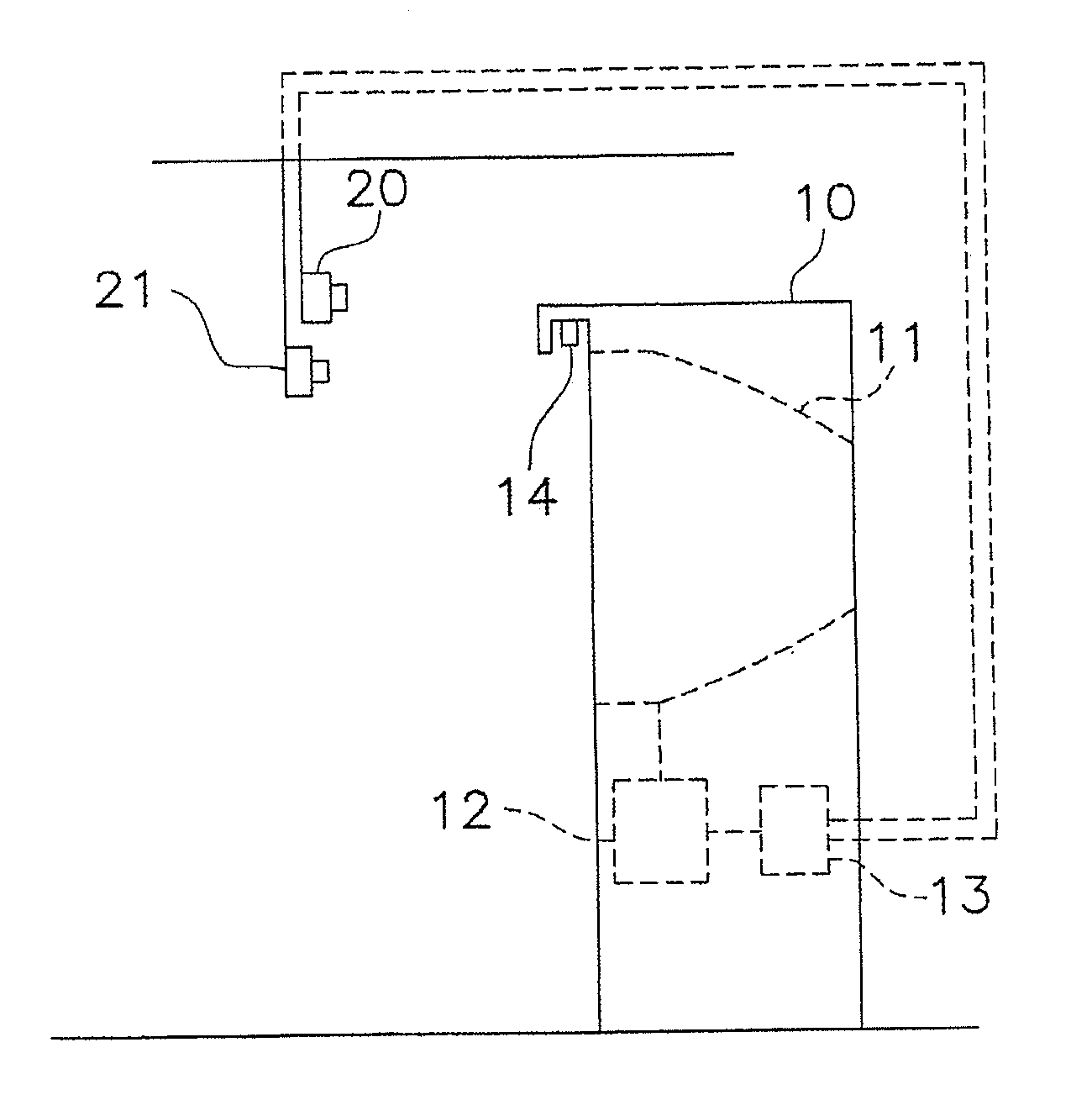
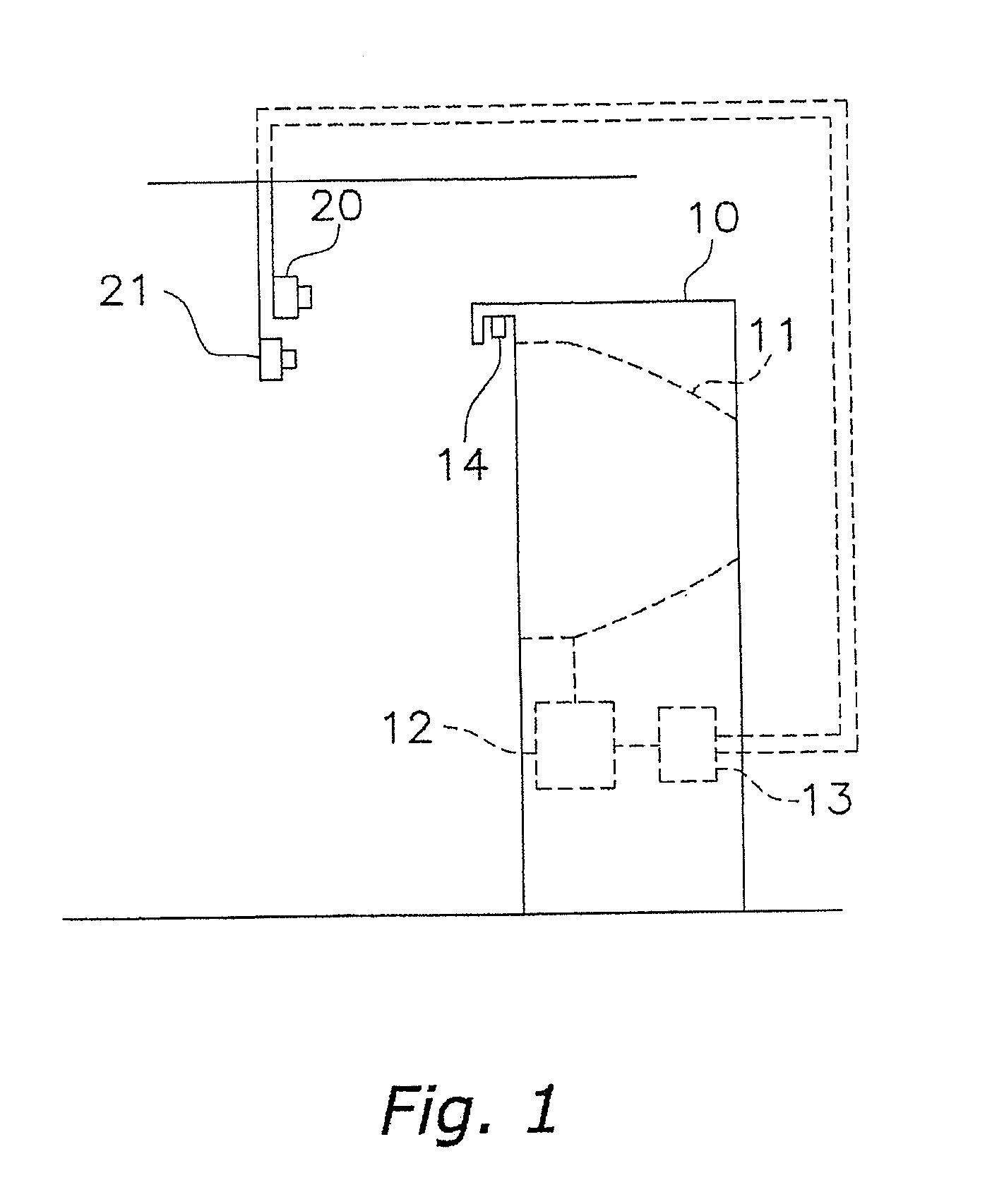
[0054]FIG. 1 is an external configuration view of a position detection system according to a first embodiment. The position detection system includes a game case 10, an infrared ray camera 20 provided at the upper front of the game case 10 (corresponding to a part of a reflected light detection means) and a color camera 21. Hereinafter, there are cases where the infrared camera 20 and the color camera 21 are collectively described as cameras 20 and 21.

[0055]The game case 10 has the following elements.

[0056](a) Display 11 (corresponding to a real screen): A display 11 is provided at the upper center of the case and outputs an image from a game machine that will be explained later.

[0057](b) Game machine 12: A game machine 12 executes a given game and outputs an image of the game that is being executed to the display 11. In the present embodiment, the game machine 12 executes a game in which a player throws a ball (corresponding to an object to be d...


PUM


Abstract

Positions of a plurality of objects in a space are detected. A position of reflected light of an object passing through an infrared screen is specified by analyzing an image obtained by selectively imaging the infrared rays. When the infrared screen is formed in front the display, reflected light is only caused just in front of the display. When the infrared rays are selectively imaged, a picture displayed with visible light is separated from reflected light in the infrared region, and only the reflected light can be imaged. A position of the reflected light on the display can be specified by a publicly known image analysis technique.

Description

CROSS-REFERENCE TO RELATED APPLICATIONS[0001]This application is a continuation application of International Patent Application number PCT / JP2006 / 313818 filed on Jul. 12, 2006, which claims priority to Japanese patent application number JP2005-218132, filed on Jul. 28, 2005. The entire disclosure of International Patent Application number PCT / JP2006 / 313818 is hereby incorporated herein by reference.BACKGROUND OF THE INVENTION[0002]1. Field of the Invention[0003]The present invention relates to a system for detecting a position of an object. More specifically, the present invention relates to a system for detecting a position of an object on a given plane in a space.[0004]2. Background Art[0005]There is a game in which collision detection for detecting collision of a real object that a player operates in a real space with a virtual object in a game space is performed. There is a game in which a player hits a ball at a virtual object that is displayed on a display as one kind of game ...

Claims


Application Information

Patent Timeline
IPC IPC(8): G01J3/00A63B63/00A63F9/02A63F13/213A63F13/219A63F13/25A63F13/426A63F13/55A63F13/837G01B11/00
CPCA63B24/0003G06F3/0425A63B2024/0043A63B2220/05A63B2220/806A63F9/02A63F9/0291A63F13/04A63F2300/1043A63F2300/1068A63F2300/1087A63F2300/8023A63F2300/8029F41J5/08G06F3/0421A63B63/00A63F13/20A63F13/21A63F13/216A63F13/213A63F13/52G06F3/0308
Inventor YOSHIDA, SATORUITO, TETSUYAWATANABE, MASAKATSUUEDA, SATOSHI
Owner KONAMI DIGITAL ENTERTAINMENT CO LTD
Why Eureka
Try Eureka