Projector

a projector and projection technology, applied in fixed installations, lighting and heating apparatus, instruments, etc., can solve the problems of reducing the performance of the projector, the incident angle of light entering from the position having the height of the image into the peripheral area of the liquid crystal display panel becomes large, etc., to achieve the effect of enhancing the brightness of the light on the liquid crystal display panel and relatively easy reduction of the number of the illumination system

Inactive Publication Date: 2008-07-10
COLUMBIA PEAK VENTURES LLC
View PDF1 Cites 7 Cited by
  • Summary
  • Abstract
  • Description
  • Claims
  • Application Information

AI Technical Summary

Benefits of technology

[0015]According to the projector in a further example, the combining lens disposed in the second section is a positive single lens located at a position in the range from (¼)L to (¾)L from the final end surface of the superimposing lens assuming that the distance between the final end surface of the superimposing lens and the light modulation surface of the second liquid crystal light valve is L. According to this structure, the F number of the illumination system can be relatively easily decreased when the combining lens is positioned at a distance equal to or longer than (¼)L, and thus the telecentric characteristics of the illumination system can be secured for the same reason as in the case of the combining lens disposed in the first section. When the combining lens is disposed at a distance equal to or shorter than (¾)L, the telecentric characteristics of the illumination system can be similarly secured even at the time of decreased F number.
[0016]According to the projector in a still further example of the invention, the first through third liquid crystal light valves have no micro-lens. According to this structure, the advantage of the brightness of light on the liquid crystal display panel enhanced by decreasing the F number of the illumination system achieved through the arrangement of the combining lens as above can be utilized in the optical system located downstream from the liquid crystal display panel. That is, when the liquid crystal display panel including the micro-lens is used, there is a possibility that light not used in the optical system disposed downstream from the liquid crystal display panel increases.

Problems solved by technology

However, when the field lens is simply removed, the incident angle of light entering from the position having the height of the image into the peripheral area of the liquid crystal panel becomes large.
In this case, the visibility angle increases and thus performance of the projector lowers (such as lowering of contrast and color unevenness).

Method used


Image

  • Projector
  • Projector
  • Projector

Examples


Embodiment Construction

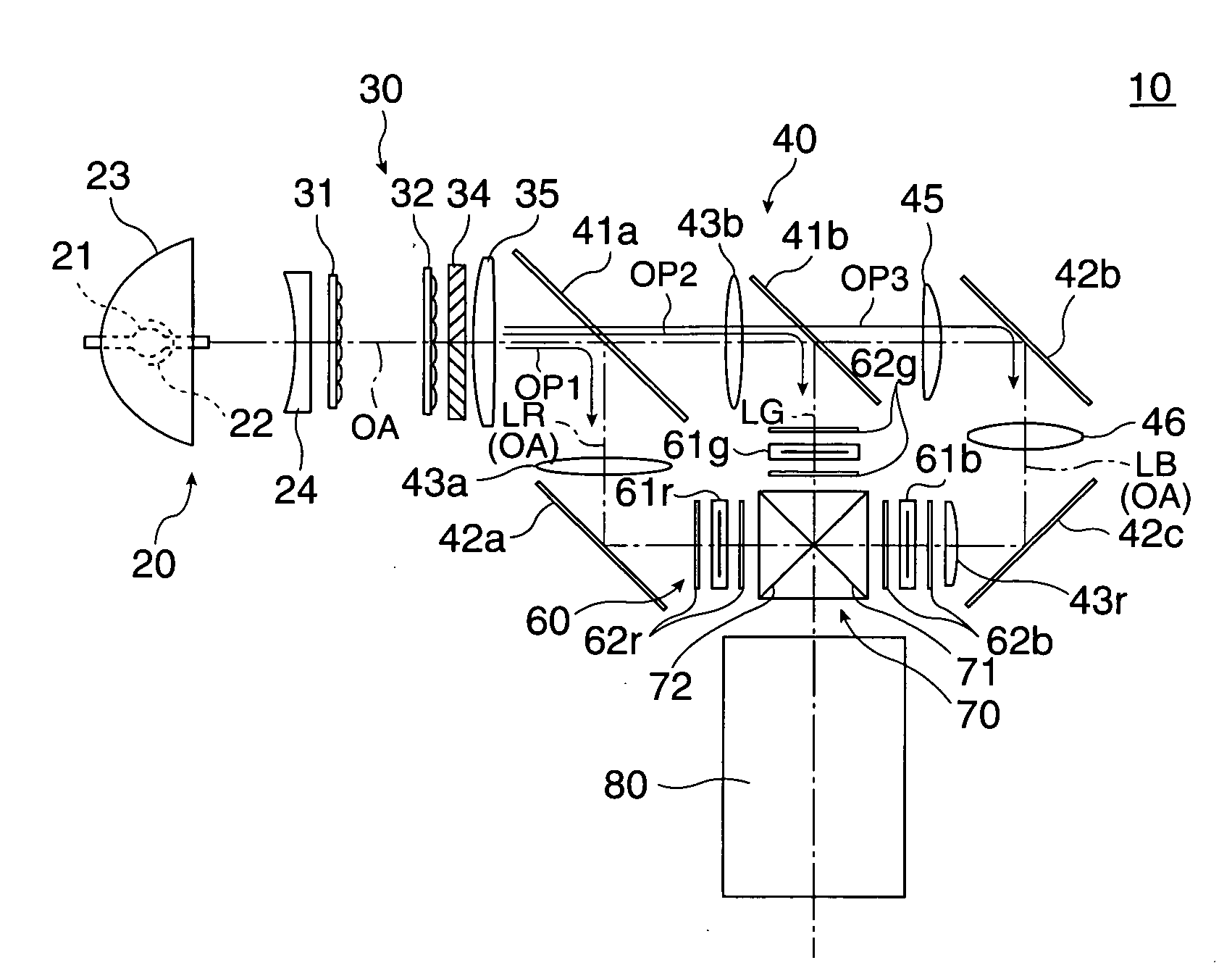
[0017]FIG. 1 illustrates a concept of a structure of optical systems included in a projector according to a first embodiment of the invention.

[0018]A projector 10 shown in the figure is an optical apparatus which modulates light emitted from a light source according to image information to form an color optical image, and enlarges and projects the optical image on a screen. The projector 10 includes a light source lamp unit 20, an illumination system 30, a color separation and light guide system 40, a light modulation unit 60, a cross dichroic prism 70, and a projection system 80. The light source lamp unit 20 and the illumination system 30 constitute a lighting device which generates illumination light entering the color separation and light guide system 40 and the like.

[0019]The light source lamp unit 20 is a light source device which converges light emitted from a lamp main body 21 toward the surroundings and emits the converged light to illuminate the light modulation unit 60 vi...


PUM


Abstract

To provide a projector capable of increasing F number of an illumination system without enlarging the size of the illumination system or the like.
A combining lens 43a operating in cooperation with a superimposing lens 35 is provided only in a first section between a first dichroic mirror 41a and a red light reflection mirror 42a as a bending mirror on a first optical path OP1 extending from the superimposing lens 35 to a first liquid crystal display panel 61r. Thus, the F number of an illumination system 30 associated with blue light can be controlled with high degree of freedom, and the number of lenses constituting a color separation and light guide system 40 and the illumination system 30 does not increase. Moreover, the incident angle of illumination light does not become large around the first liquid crystal display panel 61r, and thus the telecentric characteristics of the illumination system 30 associated with blue light can be secured.

Description

TECHNICAL FIELD[0001]The present invention relates to a projector which modulates illumination light by using a liquid crystal light valve and projects the modulated image light.BACKGROUND ART[0002]A typical related-art projector includes a light source which emits substantially white light, an illumination system which equalizes light emitted from the light source and converts the equalized light into polarized light, a color separation system which divides the light having passed the illumination system into lights on three color optical paths, three liquid crystal panels illuminated by the three color illumination lights, a cross dichroic prism which combines respective images entered from the three liquid crystal panels, and a projection lens which enlarges and projects the combined image.[0003]According to this type of projector, a field lens is provided opposed to and in the vicinity of each light entrance surface of the liquid crystal panels such that the illumination system ...

Claims


Application Information

Patent Timeline
Patent Type & Authority Applications(United States)
IPC IPC(8): G02B26/00
CPCG02B27/1046G02B27/145G02B27/149H04N9/3197H04N9/3105H04N9/3152G02B27/28
Inventor ISHIBASHI, OSAMUNISHIDA, KAZUHIRO
Owner COLUMBIA PEAK VENTURES LLC
Why Eureka
Try Eureka