Vehicle lighting assembly

a technology for lighting assemblies and vehicles, applied in the direction of vehicle components, lighting and heating apparatus, lighting apparatus, etc., can solve the problems of inability to say that the above measure is good enough, inability to effectively conceal the presence of led lamps, and inability to achieve good results, etc., to achieve effective cooling of the overall equipment and simple structure

Inactive Publication Date: 2008-07-10
TOYODA GOSEI CO LTD
View PDF6 Cites 23 Cited by
  • Summary
  • Abstract
  • Description
  • Claims
  • Application Information

AI Technical Summary

Benefits of technology

[0018]In the rear combination lamp of the present invention, the first vent hole acts as a suction hole and the second vent hole acts as an exhaust port. Since the tail/stop lamp portion whose frequency in use is high is arranged on the lower side, an updraft is generated in the housing, so that the suction via the first vent hole and the exhaustion via the second vent hole can be promoted. Also, since the first vent hole is provided near the first lamp, the first lamp is cooled by an external air that flows in

Problems solved by technology

However, since the LED lamp is arranged on the inside of the outer lens, such LED lamp is inevitably positioned insight of the observer.
As a result, even though such measures are adopted, it is difficult to conceal perfectly the presence of the LED lamp.
However, since the light leakage is caused due to light propagation/diffusion in the inside of the lens, in some cases it is impossible to say that the above measu

Method used


Image

  • Vehicle lighting assembly
  • Vehicle lighting assembly
  • Vehicle lighting assembly

Examples


first embodiment

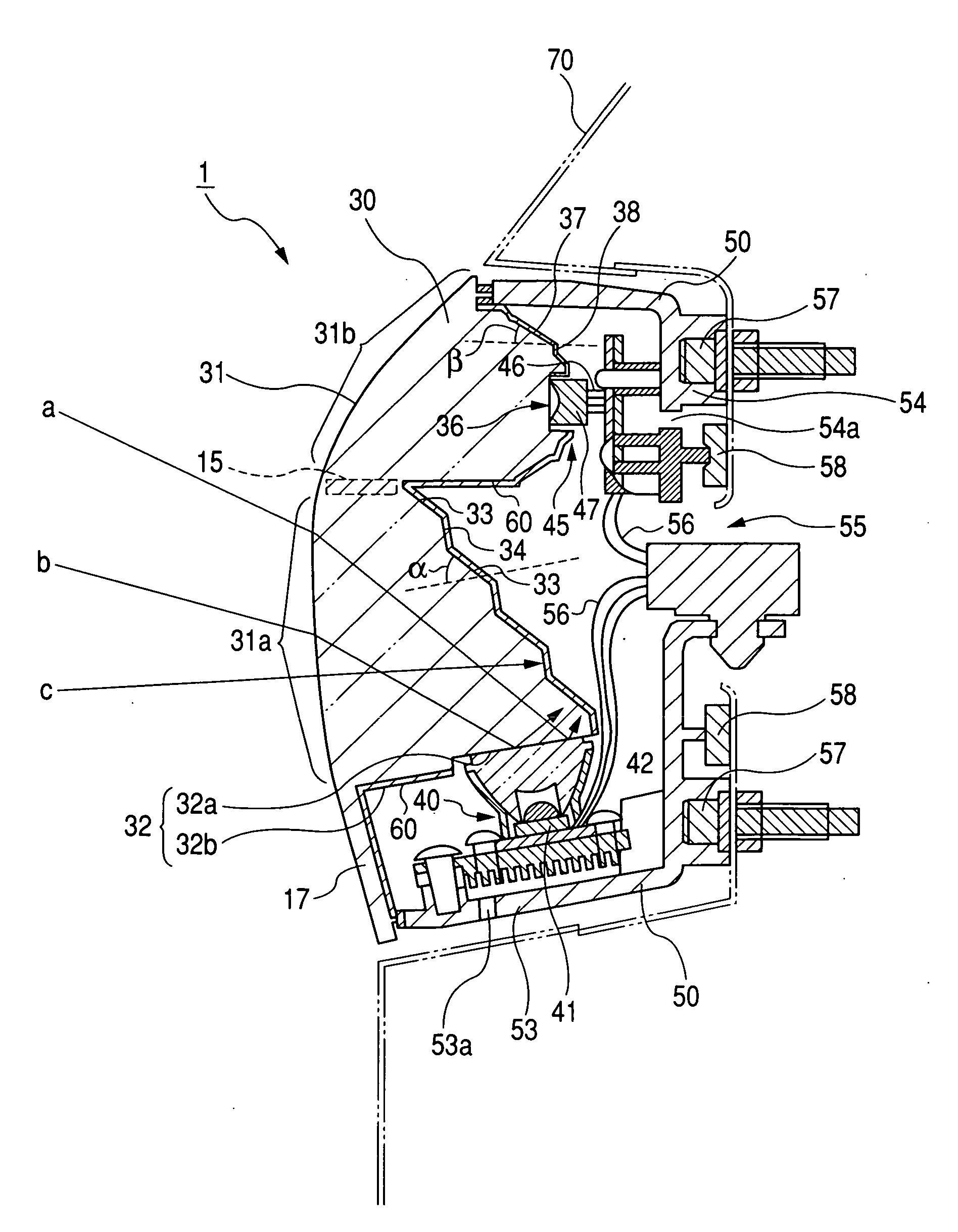
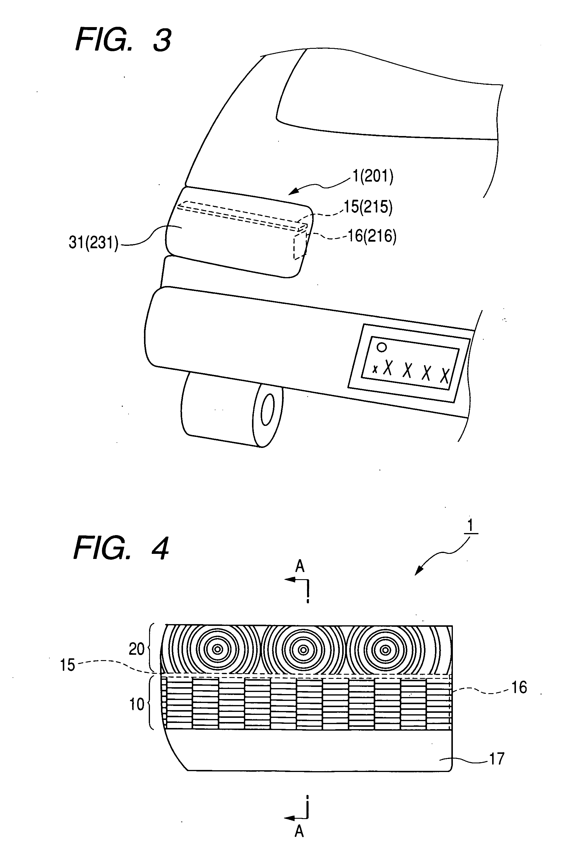
[0074]A configuration of the present invention will be explained in detail with reference to the embodiments hereunder. FIG. 3 is a perspective view showing a car body rear portion to which a rear combination lamp 1 as a first embodiment is provided. FIG. 4 is a front view of the rear combination lamp 1, and FIG. 5 is a sectional view taken along an V-V line position in FIG. 4. The rear combination lamp 1 has a tail / stop lamp portion 10 for giving a tail lamp display and a stop lamp display, and a turn lamp portion 20 for giving a turn signal display.

[0075]As shown in FIG. 5, the rear combination lamp 1 when classified roughly is constructed by a lens 30, two types of LED units (a first LED unit 40 and a second LED unit 45), and a housing 50. In the rear combination lamp 1, a light emitted from a lens front 31 of the lens 30 irradiates directly the outside. That is, the lens front 31 of the lens 30 constitutes an outer surface of the rear combination lamp 1, and as a result the pecu...

second embodiment

[0113]A perspective view of a car body rear portion to which a rear combination lamp 201 as the second embodiment of the present invention is provided is shown in FIG. 3 (similar to the first embodiment). A front view of the rear combination lamp 201 is shown in FIG. 9, and a sectional view taken along an X-X line in FIG. 9 is shown in FIG. 10. The rear combination lamp 201 has a tail / stop lamp portion 210 for giving a tail lamp display and a stop lamp display, and a turn lamp portion 220 for giving a turn signal display.

[0114]As shown in FIG. 10, the rear combination lamp 201 when classified roughly is constructed by a lens 230, two types of LED units (a first lamp 240 and a second lamp 245), and a housing 250. In the rear combination lamp 201, a light emitted from a lens front 231 of the lens 230 irradiates directly the outside. That is, the lens front 231 of the lens 230 constitutes an outer surface of the rear combination lamp 201, and as a result the peculiar stereoscopic effec...

third embodiment

[0145]A front view of a rear combination lamp 300 as the third embodiment of the present invention is shown in FIG. 13, and a sectional view taken along a XIV-XIV line in FIG. 13 is shown in FIG. 14. In this case, the same reference symbols are affixed to the like members of the rear combination lamp 201 and their explanation will be omitted herein.

[0146]As shown in FIG. 13, the rear combination lamp 300, when classified roughly, is constructed by a lens 500, two types of LED lamps (the first lamp 240 and the second lamp 245), and a housing 700. In the rear combination lamp 300, a light emitted from a lens front 510 of the lens 500 irradiates directly the outside. That is, the lens front 510 of the lens 500 is the design surface of the rear combination lamp 300, and as a result the peculiar stereoscopic effect / crystal feeling can be obtained. The rear combination lamp 300 is constructed to show positively the first lamp 240 and the second lamp 245 on the design surface (the lens fro...


PUM


Abstract

There is provided a vehicle lighting assembly, which includes a plurality of light sources, and a light guiding body having a light incident portion and a reflecting portion corresponding to the light sources on a back surface side, for emitting a light generated when a light being incident from the light incident portion is reflected by the reflecting portion from a front portion, wherein the light guiding body is divided into a plurality of blocks whose emergent light modes are different, and a reflection and diffusion area is formed on a boundary portion between two adjacent blocks.

Description

BACKGROUND OF THE INVENTION[0001]1. Field of the Invention[0002]The present invention relates to a vehicle lighting assembly and, more particularly, an improvement of a vehicle lighting assembly such as a rear combination lamp, or the like.[0003]2. Related Art[0004]In the lamp equipment such as the rear combination lamp, the high mounted stop lamp, or the like, a desired light is emitted by irradiating a light of the light source to the outside via the outer lens (design cover). For example, in the rear combination lamp using the LED lamp as the light source, as shown in FIG. 15, an LED lamp 152 is arranged on the inner side of an outer lens 151, and a reflector 153 is provided around the LED lamp 152 (see JP-A-2005-123092, for example). In such configuration, a light of the LED lamp 102 travels forward directly or via the reflector 153, and is radiated to the outside through the outer lens 151.[0005]In the above-mentioned rear combination lamp using the LED lamp as the light source...

Claims


Application Information

Patent Timeline
IPC IPC(8): B60Q1/00
CPCB60Q1/2607B60Q1/2696F21V29/004F21S48/328F21S48/215F21S43/14F21S45/47F21S45/48F21V29/70
Inventor MISAWA, AKIHIROTOTANI, CHIHARUOBA, TATSUYA
Owner TOYODA GOSEI CO LTD
Why Eureka
Try Eureka