Clad tube for nuclear fuel

a technology of nuclear fuel and clad tubes, which is applied in the field of clad tubes with rhenium liner, can solve the problems of clad/fuel failure, pitting in pure niobium materials,

Active Publication Date: 2008-07-10
BWXT NUCLEAR OPERATIONS GRP
View PDF5 Cites 1 Cited by
  • Summary
  • Abstract
  • Description
  • Claims
  • Application Information

AI Technical Summary

Problems solved by technology

This led to pitting in the pure niobium material and, ultimately, to clad / fuel failure.

Method used


Image

  • Clad tube for nuclear fuel
  • Clad tube for nuclear fuel
  • Clad tube for nuclear fuel

Examples


Embodiment Construction

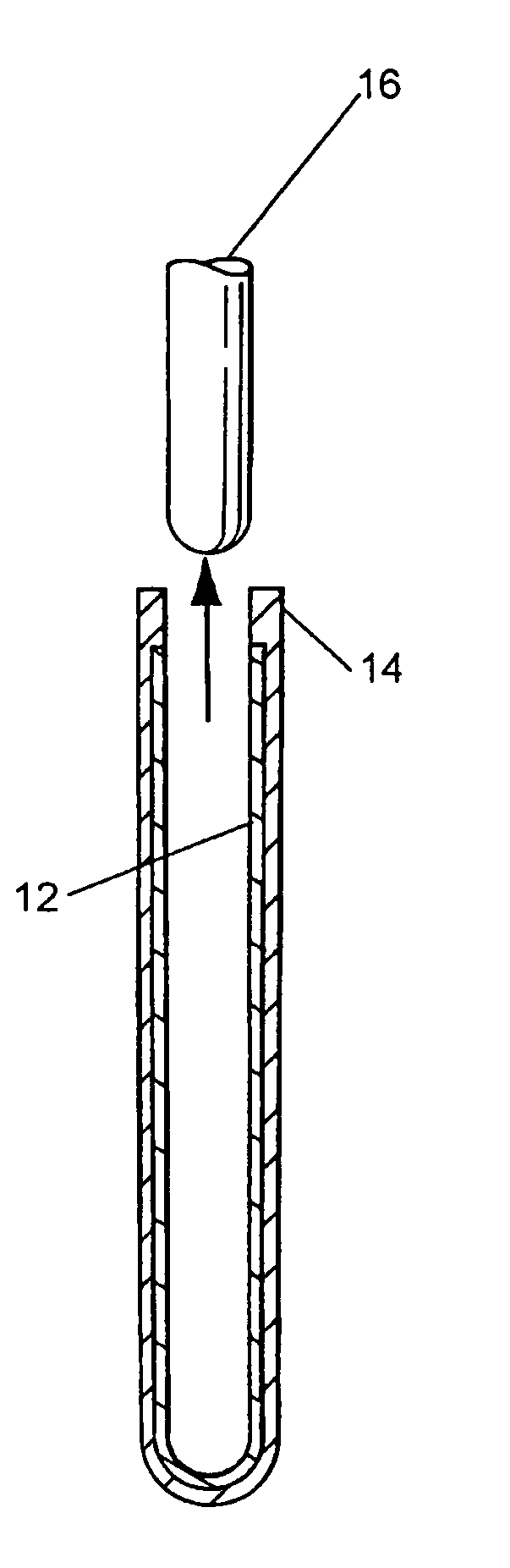
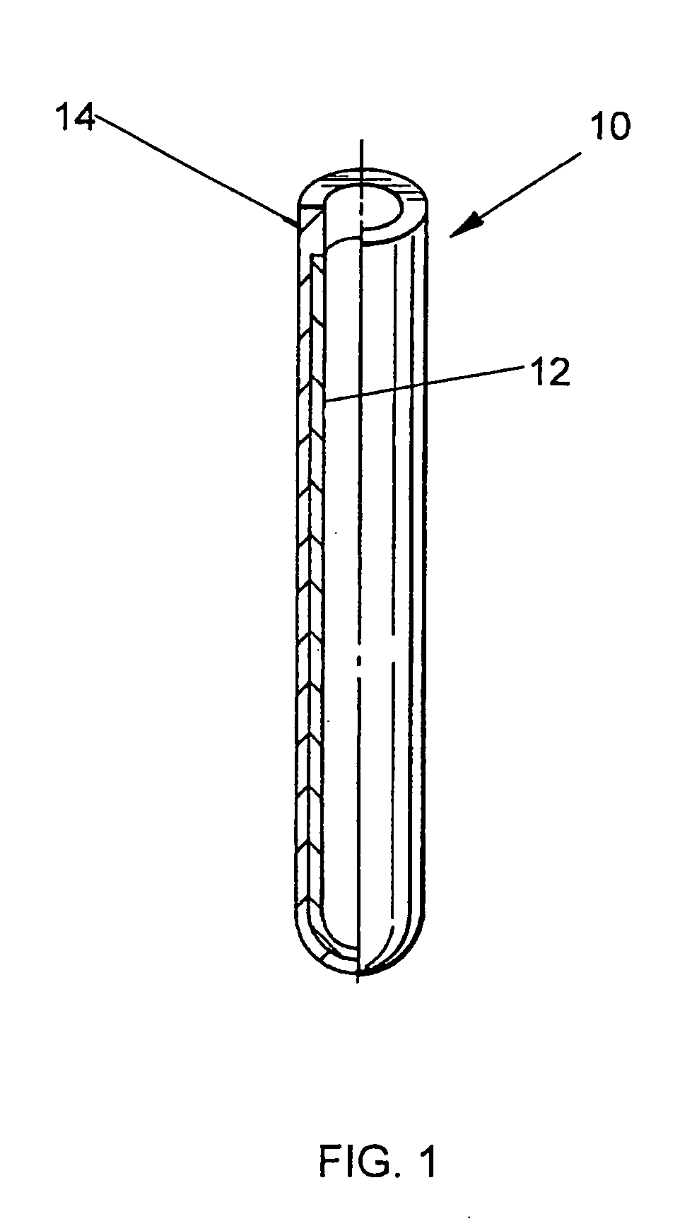
[0017]Referring to the drawings, FIG. 1 illustrates an example of a clad tube formed by the process described below. The tube 10 is generally comprised of an inner liner of rhenium 12 and outer layer of niobium alloy 14.

[0018]The process of forming the tube is comprised of several steps.

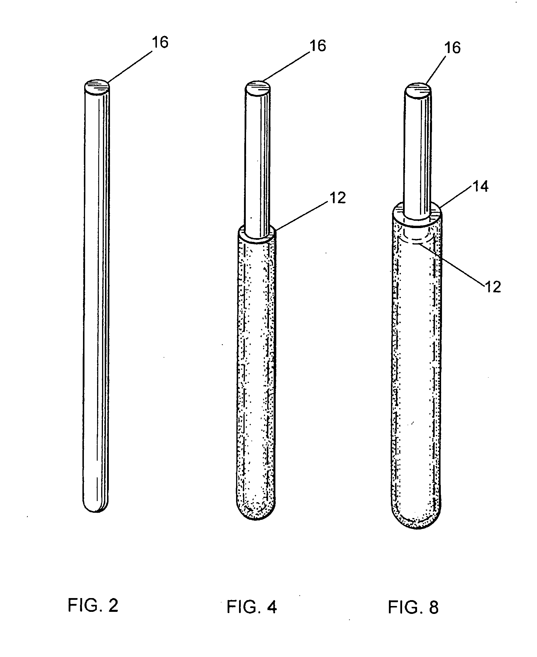
[0019]A graphite mandrel 16, seen in FIG. 2, that has been machined to the desired final geometry of the inner diameter of the tube 10 is placed in an electro deposit chamber 18 as the cathode material as illustrated in FIG. 3.

[0020]Rhenium stock 20 is placed in the electro deposit chamber 18 as the anode material. It is preferable to use refined rhenium. The chloride electrolyte 22 is placed in the electro deposit chamber 18. The chamber 18 is sealed and heating elements 24 are used to heat the electrolyte 22 to a desired temperature at less than 800 degrees Celsius. The electrolyte is a non-toxic molten salt mixture. Current and voltage are applied from a power source 26 to the mandrel cathode 16 a...


PUM

PropertyMeasurementUnit
temperatureaaaaaaaaaa

Abstract

A rhenium lined niobium alloy tube for use as a clad tube for nuclear fuel in a nuclear reactor. The tube is produced by an electro deposit process. A graphite mandrel is placed in the electro deposit chamber as the cathode material. Refined rhenium stock is used as the anode material. The chamber is filled with the chloride electrolyte. The chamber is closed and the electrolyte bath is heated. Current and voltage applied across the anode and cathode cause the rhenium to be deposited on the mandrel. Refined niobium alloy is then used as the anode material and applied over the rhenium on the mandrel to a desired thickness. The part is removed from the chamber and ground to the desired outside diameter. The graphite mandrel is removed from the tube.

Description

BACKGROUND OF THE INVENTION[0001]1. Field of the Invention[0002]The invention is generally related to nuclear fuel rods and more particularly to a clad tube with a rhenium liner that is produced by an electro deposit process.[0003]2. General Background[0004]Numerous materials have been investigated for use as cladding for uranium nitride nuclear fuel. Near the end of the SP-100 space nuclear reactor program clad development was focused on a fuel pin design having a Nb (niobium)-1% Zr (zirconium) outer shell with a rhenium liner. The purpose of this design was two-fold. First was that the 1% Zr would be reduced by the free contaminant oxygen found in the niobium alloy. Second was that the rhenium also provided a boost in creep strength over an unlined Nb-1% Zr tube. The outer niobium alloy was generally a powder metallurgy fabricated tube that typically had trace (˜1,000 ppm) impurities of oxygen. Since lithium was to be the reactor coolant, any free oxygen was scavenged from the cla...

Claims


Application Information

Patent Timeline
Patent Type & Authority Applications(United States)
IPC IPC(8): G21C3/07B32B1/08B32B15/02C25D1/02
CPCC25D1/02C25D1/20C25D5/10Y10T428/12819G21C3/07Y02E30/40Y10T428/12771C25D5/54Y02E30/30
Inventor CARMACK, WILLIAM J.HARTLESS, LEWIS C.HALFINGER, JEFFREY A.
Owner BWXT NUCLEAR OPERATIONS GRP
Why Eureka
Try Eureka