[0005]Proceeding from the cited disadvantages of the solutions of the known prior art, the invention is therefore based on the object of designing a multiple-row angular contact antifriction bearing which is distinguished in comparison with multiple-row angular contact ball bearings by a minimized axial and radial installation space with identical or increased loadbearing capability and by low production and material expenditure and therefore by low production costs, and by way of which increased wear of the raceways of the rolling bodies which results from a
high surface pressure and a high edge stress as a result of the rolling bodies is avoided effectively and therefore the service life of the angular contact antifriction bearing is increased.DESCRIPTION OF THE INVENTION
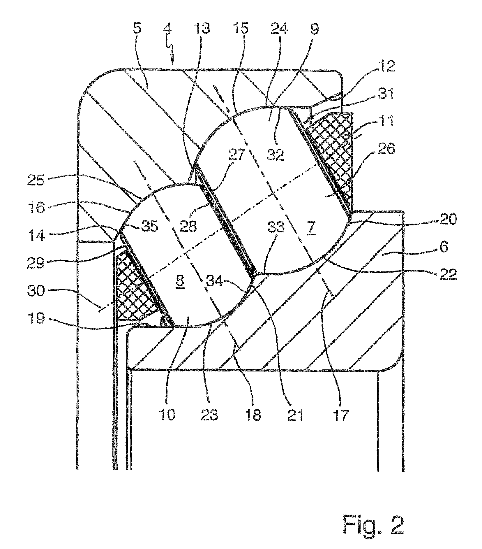
[0007]The solution according to the invention is therefore based on the realization that it is possible, as a result of the use of spherical disks as rolling bodies, in which those regions of a ball which are not in rolling contact with the raceways anyway are omitted, to realize a narrow raceway spacing between the individual rolling body rows and thus to achieve an axial installation space which is smaller by from 10% to 20% for the bearing than multiple-row angular contact ball bearings, without having to accept reductions in the loadbearing capability of the angular contact antifriction bearing. Moreover, a further realization of the invention lies in the fact that the parallel side faces which are produced on the spherical disks can be used at the same time for automatic mutual guidance of the spherical disks in their raceways, with the result that, in conjunction with the rotational axes which are variable in ball bearings but remain constant in spherical disks and in interaction with a corresponding bearing cage, an offset which is probable in rolling bodies of this type can be almost precluded.
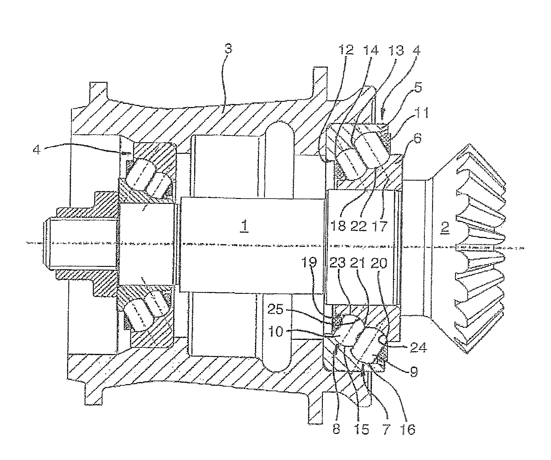
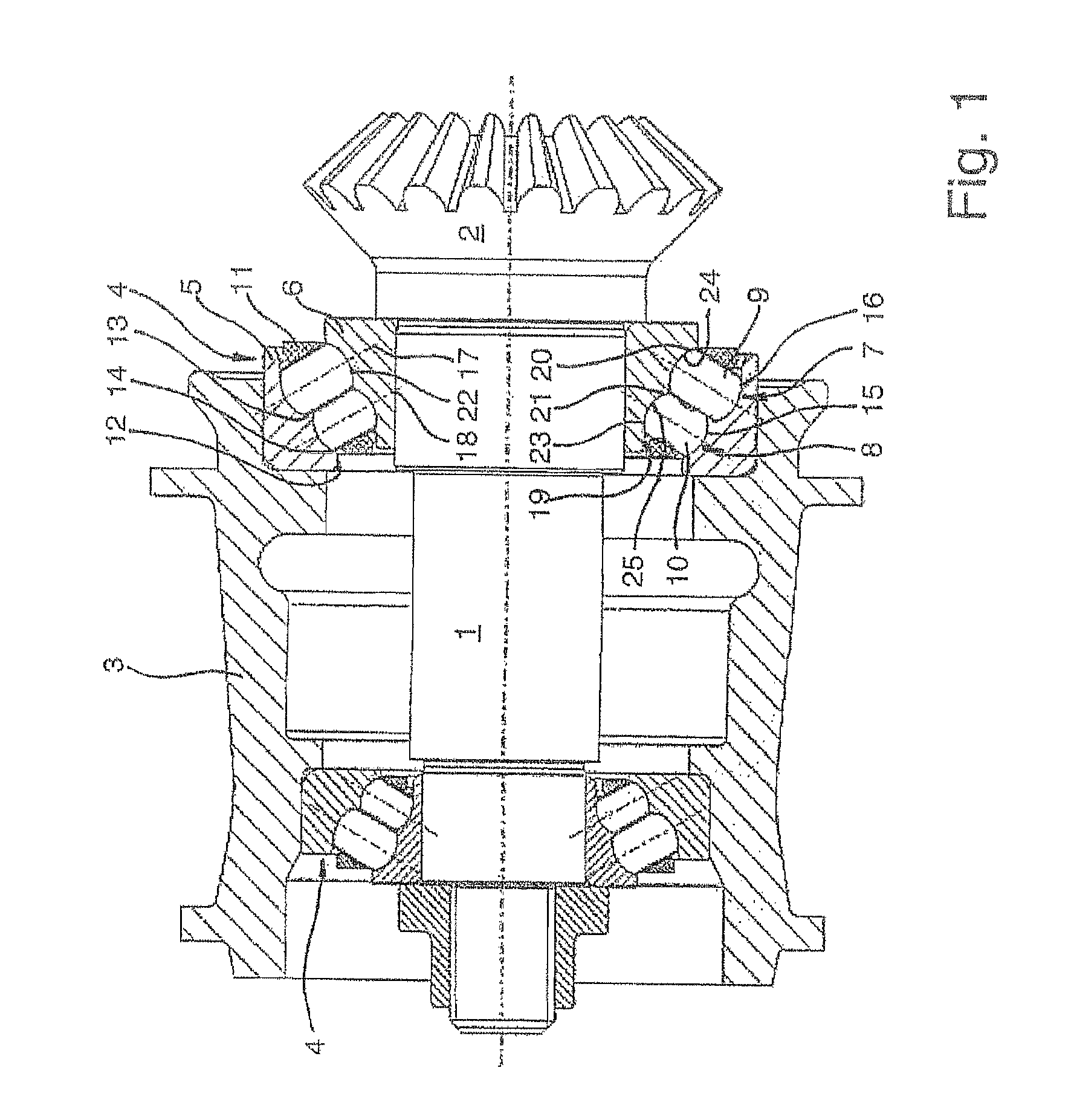
[0010]Proceeding from the above-described embodiment, it is a further feature of the angular contact antifriction bearing which is configured according to the invention, as claimed in claim 3, that the rolling bodies of each row preferably have different widths between their side faces or, as an alternative, are configured with the same width between their side faces. With regard to this, in the case of the mounting of the pinion bevel shaft in a motor vehicle rear axle differential by two angular contact antifriction bearings which are configured with two rows of spherical disks each and have different bearing diameters, it has also proven advantageous with regard to the radial and axial forces which are to be absorbed to configure the respectively first row of the spherical disks which is closest to or furthest from the bevel pinion, proceeding from a larger basic spherical shape, with a greater width between their side faces and to provide a smaller width between their side faces for the running faces of the second row of the spherical disks, proceeding from a smaller basic spherical shape. However, in other applications of a double-row angular contact antifriction bearing according to the invention, it can also be advantageous to configure each row of the spherical disks with the same width or, in the case of angular contact antifriction bearings having more than two rows of spherical disks, to configure the individual rows of the spherical disks with identical and nonidentical widths and to combine them with one another in every possible form.
[0011]Moreover, in accordance with claim 4, the angular contact antifriction bearing which is configured according to the invention is also distinguished by the fact that the rolling bodies, which are arranged in each case on a
transverse axis, of each row are preferably arranged in a common pocket of the bearing cage which is preferably configured as a window cage. This has proven advantageous, in particular, in the case of angular contact antifriction bearings which are configured according to the invention and have more than two rows of spherical disks arranged next to one another, since the
assembly costs for the bearing can be reduced considerably as a result. In the case of angular contact antifriction bearings which are configured according to the invention and have only two rows of spherical disks arranged next to one another, like those for mounting the bevel pinion shaft in a motor vehicle rear axle differential, it is also possible, however, to guide the spherical disks of both rows in the separate pockets of two comb-type cages or snap-action cages instead of in the common pocket of a window cage.
[0012]Furthermore, in accordance with claim 5, it is an expedient development of the angular contact antifriction bearing which is configured according to the invention that the running faces of the rolling bodies of each row preferably have the same
radius as their raceways in the bearing rings and are in linear contact with the latter. Since, in contrast to conventional bearing balls, the spherical disks have a constant
rotational axis, it is therefore possible to configure both the running faces of the spherical disks and the raceways in the bearing rings with the same
radius and therefore, instead of the disadvantageous punctiform contact which occurs in known angular contact ball bearings between the rolling bodies and the raceways, to realize an advantageous linear contact, by which a uniform
surface pressure with a
low stress level between the rolling bodies and the raceways and at the same time an increase in the loadbearing capability of the angular contact antifriction bearing are achieved.
[0014]The multiple-row angular contact antifriction bearing which is configured according to the invention therefore has the
advantage over the angular contact antifriction bearings which are known from the prior art that, as a result of the use of spherical disks as rolling bodies, it is distinguished by a minimized axial and radial installation space with identical or increased loadbearing capability, above all in comparison with multiple-row angular contact ball bearings. Since spherical disks of this type can be produced similarly inexpensively as conventional ball bearings and the production expenditure of an angular contact antifriction bearing which is configured according to the invention is comparable with that of an angular contact
ball bearing, favorable production costs for the angular contact antifriction bearing which is configured according to the invention can also be assumed as a result of the reduced material expenditure and the reduced weight. Moreover, the increased wear of the raceways of the rolling bodies which results in the case of known angular contact ball bearings from a high
surface pressure and a high edge stress as a result of the rolling bodies can be avoided effectively by the linear contact between the rolling bodies and their raceways and by the configuration of the running faces of the rolling bodies with a logarithmically falling profile, with the result that angular contact antifriction bearings which are configured in this way also have an increased service life. The application range of angular contact antifriction bearings which are configured according to the invention is not restricted only to the double-row application which is mentioned by way of example for mounting the bevel pinion shaft in a motor vehicle rear axle differential but, in addition to many other possible applications, can also be extended individually to fixed bearings for mounting the main spindle of
machine tools or also to four-row wheel bearings of motor vehicles in a double arrangement in an inverted mirror-image fashion directly next to one another. It is likewise conceivable to configure double-row or multiple-row radial antifriction bearings having rolling bodies which are arranged level next to one another with the same features according to the invention as the above-described angular contact antifriction bearing.

