
Backward compatible connector system

a backward compatibility and connector technology, applied in the direction of coupling devices, two-part coupling devices, coupling device connections, etc., can solve the problems of reducing the size of electronic devices or otherwise modifying, and achieve the effects of maintaining backward compatibility, compact and monolithic design, and preserving alignment capability

Inactive Publication Date: 2008-07-10
APPLE INC
View PDF15 Cites 22 Cited by
  • Summary
  • Abstract
  • Description
  • Claims
  • Application Information

AI Technical Summary

Benefits of technology

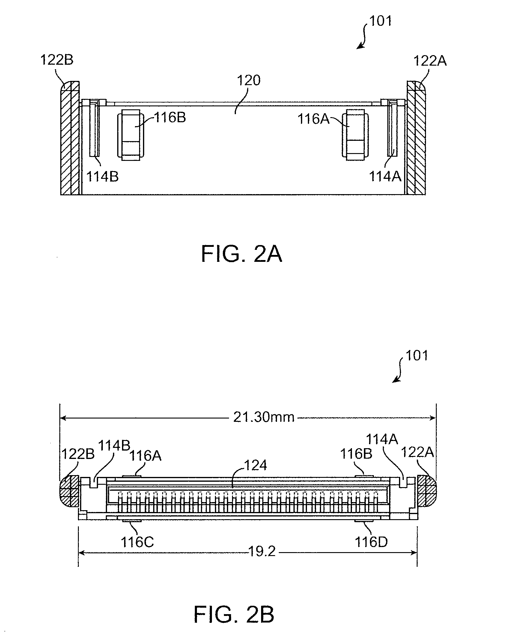
[0004]Various embodiments of the present invention provide improved connector systems with more compact and monolithic design while maintaining backward compatibility. In one embodiment, alignment posts on the two sides of a plug connector are substantially removed and the remaining connector shell reshaped so as to preserve alignment capability. The reshaped connector includes, in one embodiment, a shell that is made of a single sheet of conductive material wrapped around the connector forming a single seam. Other pre-existing features such as alignment grooves and some or all springy raised tabs can be eliminated resulting in a more compact and monolithic structure for the connector without impacting functionality or backward compatibility. In another embodiment, a trim ring is molded to the base of the connector to form an integrated unit with the connector. The integrated unit can result in reduced size for the connector when it is incorporated into other devices such as a docking station. In yet another embodiment, a printed circuit board is integrated into the boot of a connector assembly to act as an intermediate connection mechanism between the cable wires and the connector pins. Other functionality such as identification circuitry or electrostatic discharge protection circuitry can be incorporated on to the integrated printed circuit board.
[0006]In another embodiment, the plug connector further includes an integrated trim ring molded to a base of the plug connector. In a specific embodiment the integrated trim ring is made of glass reinforced nylon. In a further embodiment, the number of barbs that hold in place an electrode inside the plug connector is reduced.

Problems solved by technology

On the other hand, the ever present demand for reducing the size of electronic devices or otherwise modifying their structure for other industrial design considerations, particularly in the handheld consumer electronics market, often requires a redesign of many aspects of the device including the connectors.

Method used


Image

  • Backward compatible connector system
  • Backward compatible connector system
  • Backward compatible connector system

Examples


Embodiment Construction

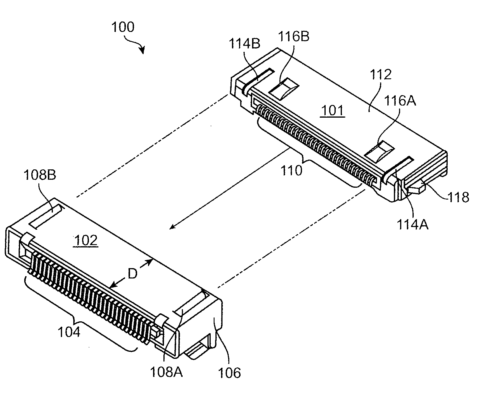
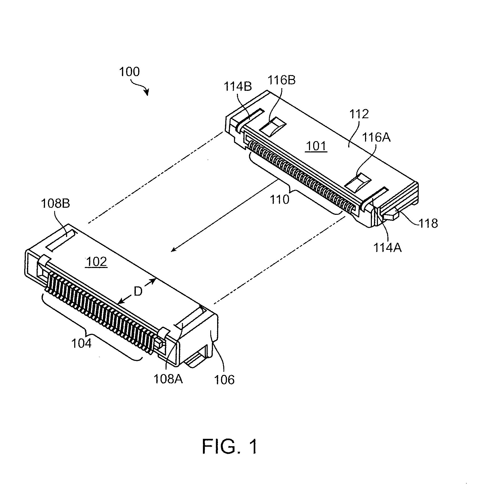
[0019]Referring to FIG. 1, there is shown a connector system 100 that is currently in use by a vast array of electronic devices including handheld media players such as the iPod™ and a host of accessories developed for such handheld media players. Connector system 100 includes a plug connector 101 that is insertable into a receptacle connector 102. The connectors are designed such that when in mating position, an array of pins 110 housed in plug connector 101 are in contact with a corresponding array of pins 104 housed in receptacle connector 102. To properly align the two arrays of pins during the insertion process, receptacle connector 102 includes a pair of projections 108A and 108B that project from its outer shell inwardly. In one embodiment, projections 108A and 108B are formed by cutting the top plate of the connector shell in an angled C (or bracket) shape and bending the resulting tongue pieces toward the interior of the plug housing. Plug connector 101 in turn includes a c...


PUM


Abstract

Various embodiments of connectors and connector assemblies provide modified structural features to meet evolving industrial design requirements while maintaining backward compatibility. In one embodiment, alignment posts on the two sides of a plug connector are substantially removed and the remaining connector shell reshaped so as to preserve alignment capability. Other pre-existing features such as alignment grooves and some or all springy raised tabs can be eliminated resulting in a more compact and monolithic structure for the connector without impacting functionality or backward compatibility. In another embodiment, a trim ring is molded to the base of the connector to form an integrated unit. The integrated unit results in a reduced size of the connector when it is incorporated into other devices such as a docking station. In yet another embodiment, a printed circuit board is integrated into the boot of a connector assembly to act as an intermediate connection mechanism between the cable wires and the connector pins. Other functionality such as identification circuitry or electrostatic discharge protection circuitry can be incorporated on to the integrated printed circuit board.

Description

CROSS-REFERENCES TO RELATED APPLICATIONS[0001]This application is related to U.S. Pat. No. 6,776,660, titled “Connector,” and commonly-assigned patent application Ser. No. 10 / 833,689, titled “Connector Interface System for Multi-Communication Device,” filed Apr. 27, 2004 (20750P-000500US / P3393US1), and Ser. No. 10 / 423,490, titled “Media Player System,” filed Apr. 25, 2003 (20750P-000900US / P3032US1), all three of which are hereby incorporated by reference.BACKGROUND OF THE INVENTION[0002]The present invention relates in general to connectors for electronic systems. More particularly, the invention relates to various implementations of and methods of manufacture for connector systems that connect portable or handheld devices to other electronic devices.[0003]The last half decade has witnessed a rapid proliferation of handheld consumer electronic devices such as mobile phones, digital media players, personal digital assistants and the like. The connector technology that enables electri...

Claims


Application Information

Patent Timeline
IPC IPC(8): H01R29/00H01R12/71
CPCH01R13/504H01R13/64H01R12/7076H01R13/74H01R12/716H01R13/6658
Inventor MURPHY, R. SEANCROOIJMANS, WIMHOWARTH, RICHARDSTRINGER, CHRISTOPHER
Owner APPLE INC
Learn More