Apparatus, system, and method for data storage using progressive raid

a data storage and progressive raid technology, applied in the field of data storage, can solve the problems of slow data access time, relatively slow data writing, and slow data reading, and achieve the effect of fast data writing and data reading

Active Publication Date: 2008-07-10
SANDISK TECH LLC
View PDF89 Cites 169 Cited by
  • Summary
  • Abstract
  • Description
  • Claims
  • Application Information

AI Technical Summary

Benefits of technology

[0036]Another method of the present invention is also presented for reliable, high performance storage of data. The method includes receiving an updated data segment. The updated data segment corresponds to an existing data segment of an existing stripe. A stripe includes data from a file or object divided into one or more stripes. Each stripe includes N data segments and one or more parity data segments. The N data segments are stored on storage devices of a set of storage devices assigned to the stripe. Each of the parity data segments is generated from the N data segments of the stripe and stored on one or more parity-mirror storage devices assigned to the stripe. The set of storage devices include the one or more parity-mirror storage devices. The existing stripe includes N existing data segments and one or more existing parity data segments.

Problems solved by technology

A disadvantage of RAID 0 is that writes are relatively slow because written data must be written twice.
Reading data is relatively slow, however, because is data may be spread over multiple storage devices and access time of multiple storage devices is typically slower than reading data from one storage device containing all of the desired data.
In addition, RAID 1 provides no failure protection.
Nested RAID configurations typically have similar performance issues as the underlying RAID groups.

Method used


Image

  • Apparatus, system, and method for data storage using progressive raid
  • Apparatus, system, and method for data storage using progressive raid
  • Apparatus, system, and method for data storage using progressive raid

Examples


Embodiment Construction

[0061]Many of the functional units described in this specification have been labeled as modules, in order to more particularly emphasize their implementation independence. For example, a module may be implemented as a hardware circuit comprising custom VLSI circuits or gate arrays, off-the-shelf semiconductors such as logic chips, transistors, or other discrete components. A module may also be implemented in programmable hardware devices such as field programmable gate arrays, programmable array logic, programmable logic devices or the like.

[0062]Modules may also be implemented in software for execution by various types of processors. An identified module of executable code may, for instance, include one or more physical or logical blocks of computer instructions which may, for instance, be organized as an object, procedure, or function. Nevertheless, the executables of an identified module need not be physically located together, but may include disparate instructions stored in dif...


PUM


Abstract

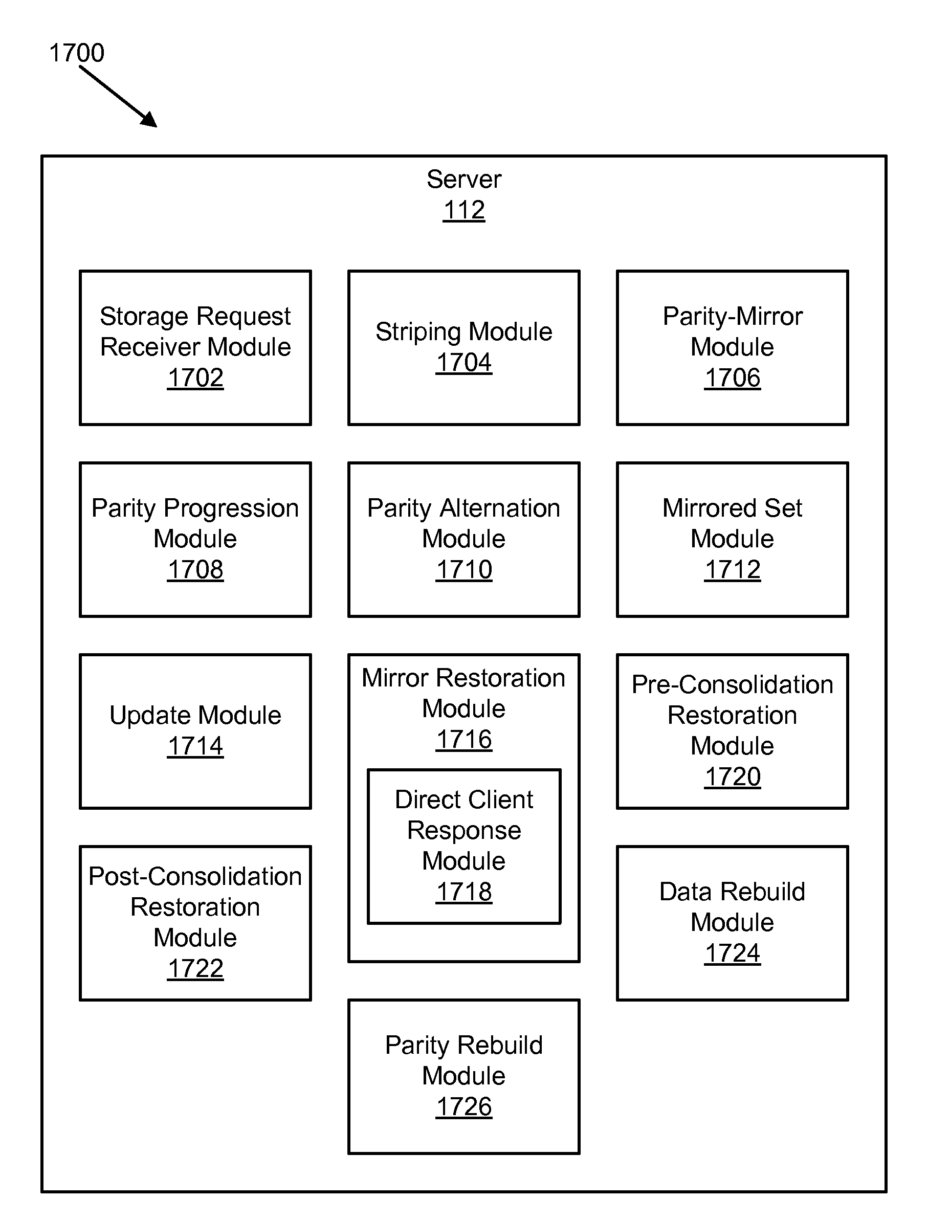
An apparatus, system, and method are disclosed for data storage with progressive redundant array of independent drives (“RAID”). A storage request receiver module, a striping module, a parity-mirror module, and a parity progression module are included. The storage request receiver module receives a request to store data of a file or of an object. The striping module calculates a stripe pattern for the data. The stripe pattern includes one or more stripes, and each stripe includes a set of N data segments. The striping module writes the N data segments to N storage devices. Each data segment is written to a separate storage device within a set of storage devices assigned to the stripe. The parity-mirror module writes a set of N data segments to one or more parity-mirror storage devices within the set of storage devices. The parity progression module calculates a parity data segment on each parity-mirror device in response to a storage consolidation operation, and stores the parity data segments. The storage consolidation operation is conducted to recover storage space and / or data on a parity-mirror storage device.

Description

CROSS-REFERENCES TO RELATED APPLICATIONS[0001]This application is a continuation-in-part of and claims priority to U.S. Provisional Patent Application No. 60 / 873,111 entitled “Elemental Blade System” and filed on Dec. 6, 2006 for David Flynn, et al., and U.S. Provisional Patent Application No. 60 / 974,470 entitled “Apparatus, System, and Method for Object-Oriented Solid-State Storage” and filed on Sep. 22, 2007 for David Flynn, et al., which are incorporated herein by reference.BACKGROUND OF THE INVENTION[0002]1. Field of the Invention[0003]This invention relates to data storage and more particularly relates to storing data using a progressive RAID system.[0004]2. Description of the Related Art[0005]A redundant array of independent drives (“RAID”) can be structured in many ways to achieve various goals. As described herein, a drive is a mass storage device for data. A drive, or storage device, may be a solid-state storage, a hard disk drive (“HDD”), a tape drive, an optical drive, or...

Claims


Application Information

Patent Timeline
Patent Type & Authority Applications(United States)
IPC IPC(8): G06F11/08
CPCG06F1/183Y02B60/1235G06F3/0656G06F3/0685G06F3/0688G06F9/52G06F11/108G06F12/0246G06F12/0804G06F12/0868G06F13/28G06F13/4022G06F2211/103G06F2212/222H05K7/1444H05K7/1487H04L67/1097H04L67/02G06F12/121G06F13/426G06F2211/002G06F2212/69G06F2212/7205Y02B60/1225Y02B60/1228G06F3/0613G06F3/0608Y02D10/00G06F2212/7203G06F2212/7208G06F2212/1044G06F2212/1032G06F3/06G06F15/16G06F11/10G06F15/173G06F3/0604G06F3/0659G06F12/12G06F2212/2022G06F3/0619G06F3/065G06F3/0652G06F12/123G06F2212/70G06F3/0679G06F3/0643G06F9/54
Inventor FLYNN, DAVIDATKISSON, DAVIDTHATCHER, JONATHANZAPPE, MICHAEL
Owner SANDISK TECH LLC
Why Eureka
Try Eureka