
Integrated linear motor

Inactive Publication Date: 2008-07-17
HIWIN MIKROSYST
View PDF2 Cites 10 Cited by
  • Summary
  • Abstract
  • Description
  • Claims
  • Application Information

AI Technical Summary

Benefits of technology

[0009]It is one objective of the present invention to provide an integrated linear motor, which is formed by integrating a linear motor and a servo control system into a mechanism and further assembling the mechanism to a linear stage wherein all transmission of control signals and data is accomplished by means of internal electric contacts instead of external electrical wiring. Thereby, the present invention is advantageous by reduced costs for wire preparing, wire arrangement, system repair and maintenance, space saving, mitigated risk of mal operation of the system due to noise disturbance, and enhanced reliability of the system.

Problems solved by technology

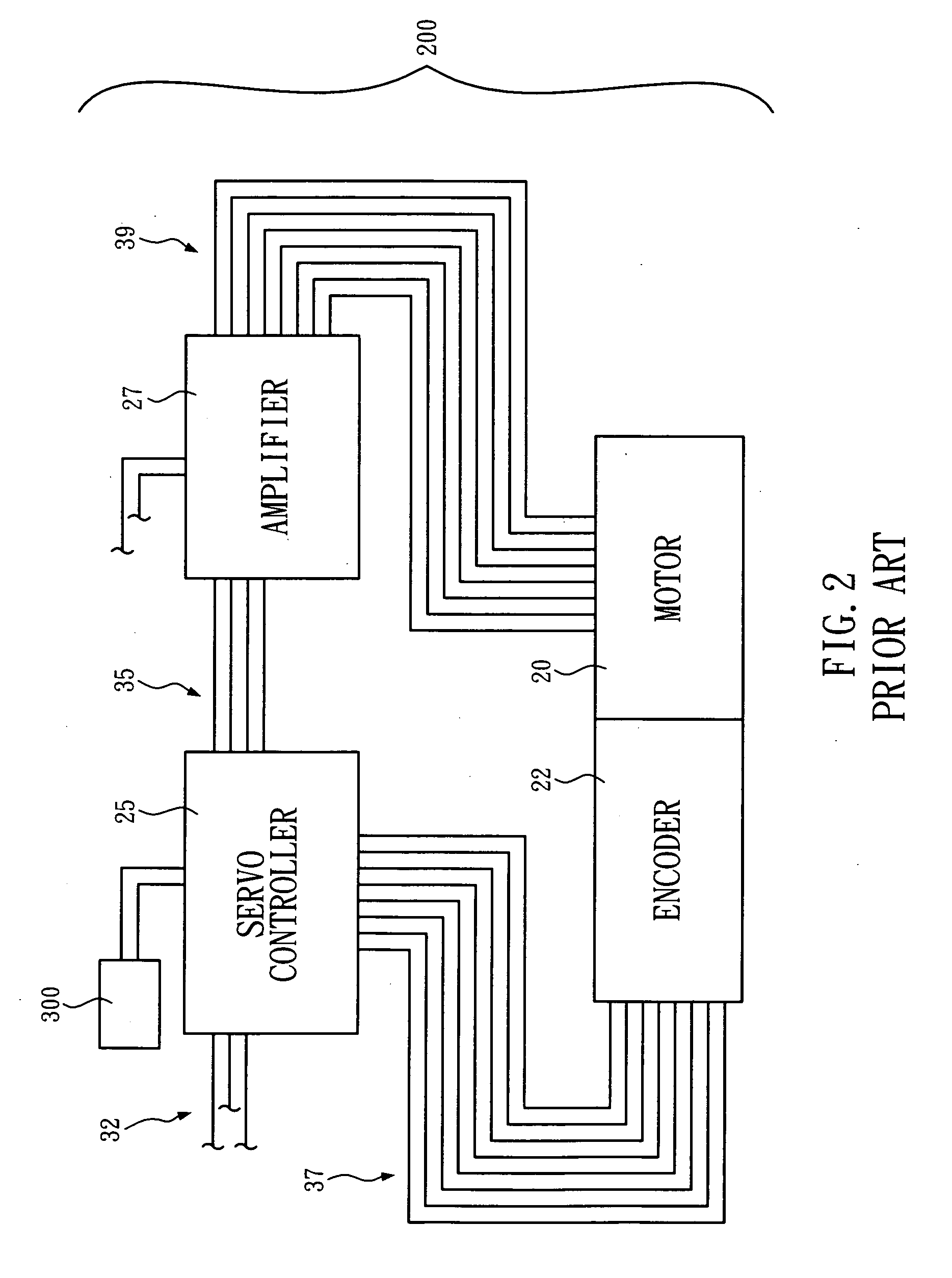
Thereupon, risks of wire-misarrangement and noise disturbance that debase the reliability of the system can be significantly increased due to the complexity of the wire arrangement and the overlong lines.
Additionally, costs and expense for wire preparing, wire arrangement, system repair and maintenance can be substantially raised for the complexity of the wire arrangement.
Through the drawing, it is even more apparent that the external wiring of the linear motor system is extremely complicated.

Method used


Image

  • Integrated linear motor
  • Integrated linear motor
  • Integrated linear motor

Examples


Embodiment Construction

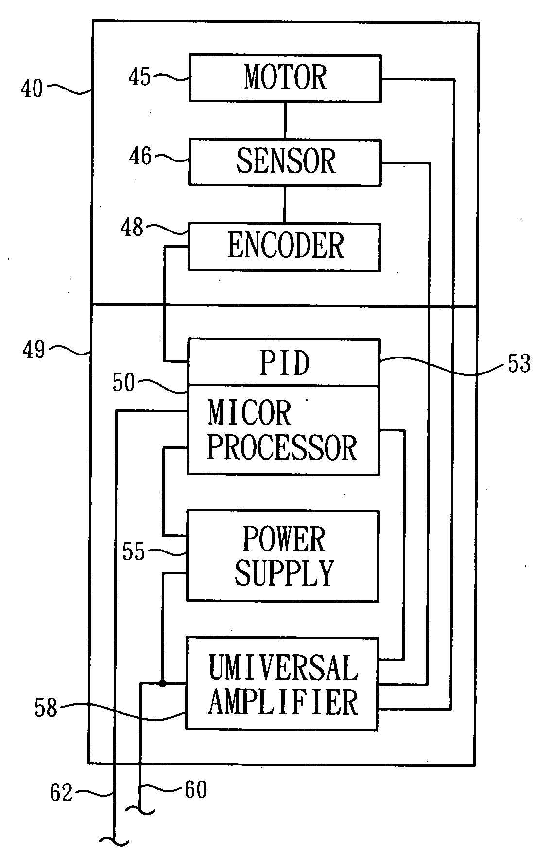
[0020]FIG. 4 graphically illustrates the system configuration of the integrated linear motor according to the present invention. As can be seen through the drawing, a Hall sensor 46, an encoder 48 and a linear motor 45 are integrated onto a stage 40. A microprocessor 50, an amplifier 58, a power supply 55 and a proportional integral derivative filter (PID filter) 53 are integrated in a controller 49 which is further coupled with the stage 40 by mechanical means. Direct current (DC) is provided to the controller 49 through a power input unit 60. Other formalized signal lines such as RS-232 are also provided to the controller 49 by way of a COM port 62.

[0021]The power input unit 60 is connected to the amplifier 58 and power supply 55 in the controller 49.

[0022]The power supply 55 functions for storing electric power and providing applicable direct current to other power demanded components of the controller 49. Signals are imported to the microprocessor 50 through the COM port 62 so a...


PUM


Abstract

The present invention provides an integrated linear motor, which comprises a linear stage and a controller coupled to the linear stage, wherein the linear stage comprises a Hall sensor, an encoder, and a linear motor integrated thereon and the controller comprises a microprocessor, an amplifier, and a power supply integrated therein.

Description

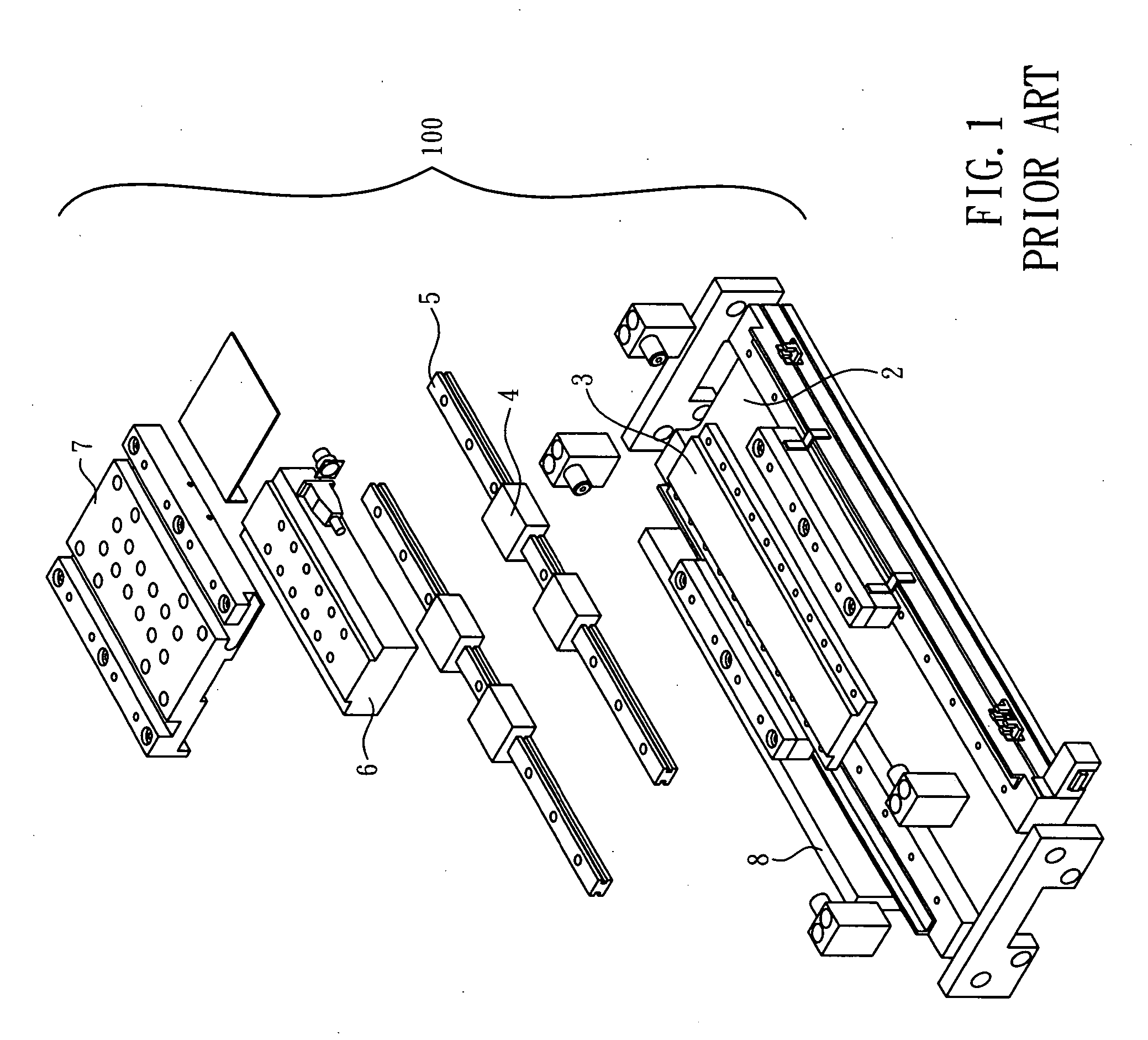
BACKGROUND OF THE INVENTION[0001]1. Technical Field[0002]The present invention relates to linear motors and, more particularly, to a solution of integrated linear motor realized by integrating a modularized controller and a linear motor to a linear stage.[0003]2. Description of Related Art[0004]A conventional linear stage 100, as shown in FIG. 1, primarily comprises a foundation 2, a stator 3, a plurality of sliders 4, a pair of slide guides 5, a forcer 6, a forcer housing 7, and a position feedback system 8.[0005]A typical servo control system 200, as shown in FIG. 2, primarily comprises a motor 20, an encoder 22 pertaining to the motor 20, a servo controller 25 and an amplifier 27 which are situated outside of the motor 20 and the encoder 22, and connected to the motor 20 and the encoder 22 by a plurality of transmission lines. The servo controller 25 comprises a power supply and a ground wire, and is connected to a computer 300 through a wire means. The amplifier 27 also comprise...

Claims


Application Information

Patent Timeline
IPC IPC(8): H02P7/00
CPCG05B2219/37094H02P6/006G05B2219/41337G05B2219/37177
Inventor CHENG, CHI-YUANLIU, MING-HSING
Owner HIWIN MIKROSYST
Learn More