
Method and device for determining the duty-cycles of pwm control signals of an inverter

a technology of pwm control signal and duty cycle, which is applied in the direction of synchronous motor starter, automatic controller, ac-dc conversion, etc., can solve the problems of simultaneous switching of two half-bridges, increased power loss, and uneven switching frequency of electronic components, so as to reduce the number of steps

Inactive Publication Date: 2008-07-17
STMICROELECTRONICS SRL
View PDF8 Cites 25 Cited by
  • Summary
  • Abstract
  • Description
  • Claims
  • Application Information

AI Technical Summary

Benefits of technology

[0019]An efficient method of determining the three duty-cycles of the three PWM control signals of an inverter that drives a three-phase load in SVM mode and that may require a reduced number of steps has now been found.
[0020]The method may advantageously exploit the fact that the three duty-cycles may be modulated, as a function of the angle γ of the phasor that represents the triplet of voltages to be applied, according to modulating signals that may be reconstructed from only two waveforms using reflection and reversal operations. By storing these two waveforms in two look-up tables, it may be possible to reconstruct the modulating signals for each value of the angle γ, with a single memory access and an addition.

Problems solved by technology

This approach has several drawbacks: uneven switching frequency of the electronic components; and the possibility of simultaneous switching of two half-bridges with a consequent increase of power losses.
In Rathnakumar et al., “A New Software Implementation of Space Vector PWM”, classic software implementations using Matlab and Psim are described that show the great complexity of the calculations required for a correct implementation of the SVM.

Method used


Image

  • Method and device for determining the duty-cycles of pwm control signals of an inverter
  • Method and device for determining the duty-cycles of pwm control signals of an inverter
  • Method and device for determining the duty-cycles of pwm control signals of an inverter

Examples


Embodiment Construction

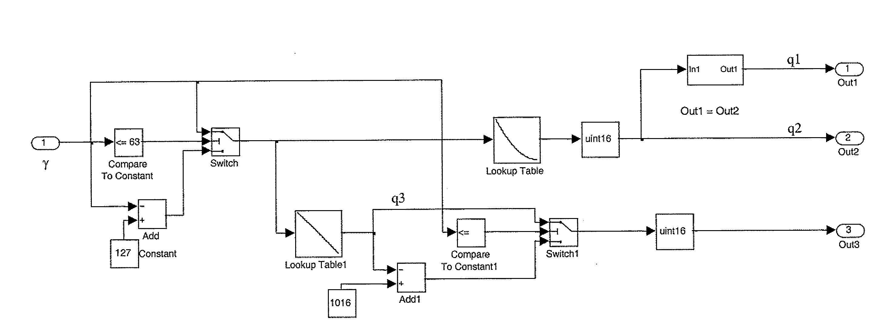
[0054]Compared to a classic SVM technique, according to a first embodiment, a single look-up table is used by accessing the look-up table once for each winding during each PWM period, thus avoiding the otherwise complex calculations necessary for determining the three duty-cycles t1, t2 and t3 that, besides making the computations of the algorithm more onerous, generally require additional hardware resources.

[0055]By reformulating equations (3), the following relations are obtained:

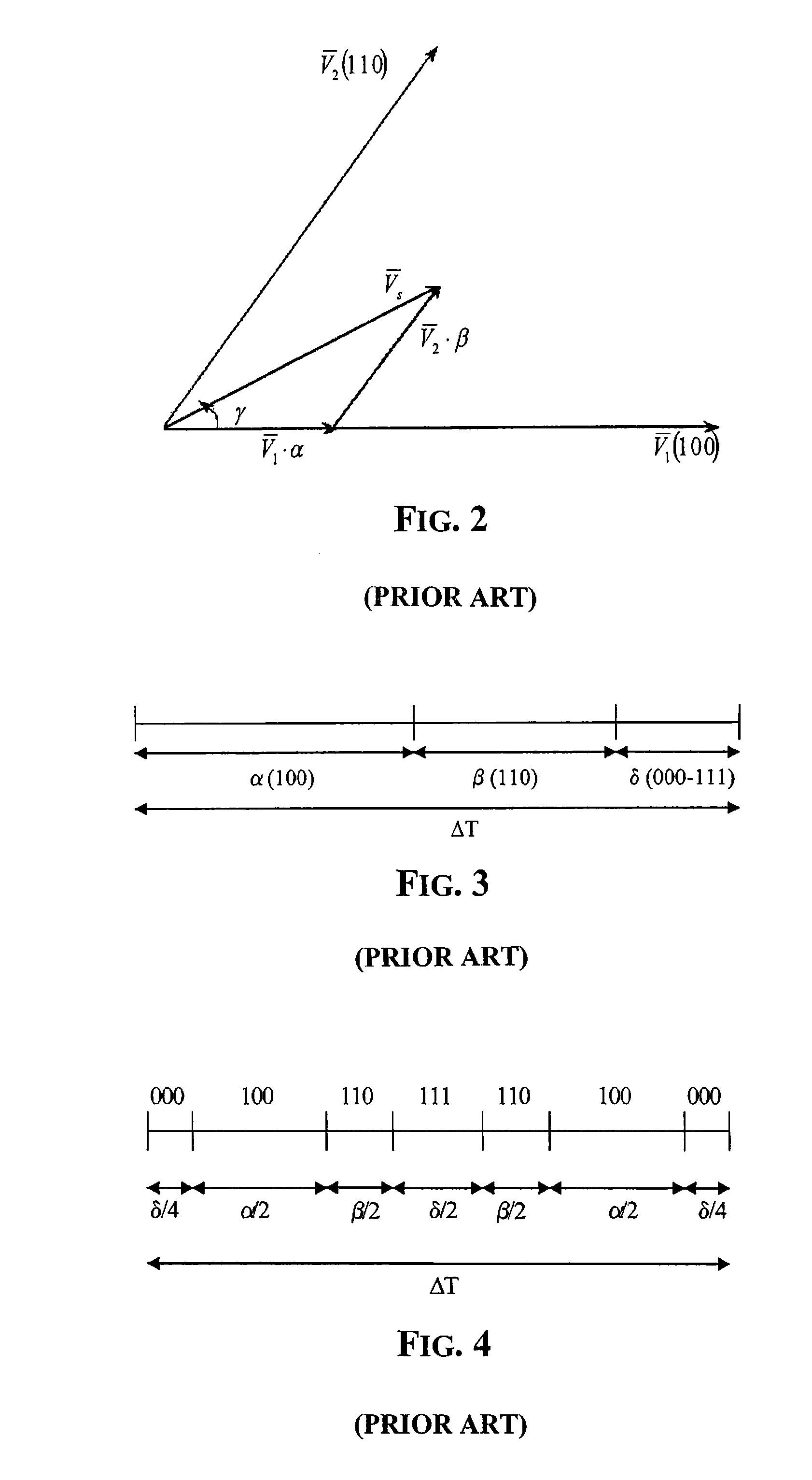
β=23·VVK·sin(γ-γK)·ΔTa=VVK·[cos(γ-γK)-13·sin(γ-γK)]·ΔTδ=ΔT-α-β(5)

(γ−γK) being the angle between VS and VK (FIG. 6). By substituting these equations in Table 1, it is noticed that t1, t2, t3 are a function of the ratio

VVK

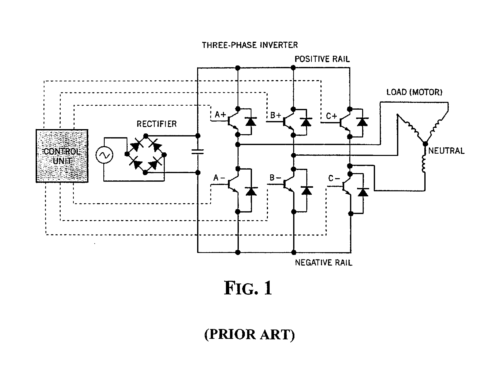
and of the angle (γ−γK), wherein VK is the supply voltage of the inverter, V is the module of the control vector VS, γ is the angle between the phasor VS and the origin of the reference, and γK is the angle of the phasor VK in respect to the origin of the reference.

[0056]It is possible to ...


PUM


Abstract

A method for determining duty-cycles of respective pulse width modulated (PWM), space vector modulated (SVM) control signals of an inverter, may include storing values of the duty-cycles as a function of a position of the multi-phase electric load in a look-up table. The method also may include determining a phasor angle representing applied sinusoidal voltages. The method also may include determining the duty-cycles as a function of the angle, and storing, in the look-up table, values of two pre-established waveforms relative to at least one duty-cycle as a function of the angle in at least two 60° degree angular sectors, by at least, identifying which of six 60° angular sectors the angle belongs, calculating a difference between the angle and an angular sector lower bound, and generating values as a function of the identified angular sector of the difference and the two pre-established waveforms stored in the look-up table.

Description

FIELD OF THE INVENTION[0001]This invention relates to control techniques of multi-phase electric loads. More particularly, the invention relates to a method and a device for establishing the duty-cycle of pulse width modulation (PWM) control signals according to a space vector modulation (SVM) mode controlling an inverter that drives a multi-phase electric load.BACKGROUND OF THE INVENTION[0002]Space Vector Modulation (SVM) is a modulation technique used for controlling induction, controlling brushless motors, and for generating sinusoidal phase voltages starting from a DC voltage source. This technique is widely used because it allows generation of large sinusoidal voltages with a total harmonic distortion (THD) smaller than classical PWM control techniques.[0003]FIG. 1 depicts a control scheme of a common three-phase motor. By driving the switches of each half-bridge with respective PWM signals, the duty-cycle of which varies with time according to a modulating signal, a generally ...

Claims


Application Information

Patent Timeline
IPC IPC(8): G05B11/28
CPCH02M7/53873
Inventor PIROZZI, FRANCESCOMEGLIO, MAURIZIO DIBARATTO, STEFANO
Owner STMICROELECTRONICS SRL
Learn More